Bridge Failure Cases
Autoroute 19 de la Concorde Overpass
The de la Concorde Overpass over Autoroute 19 in Laval, Quebec, collapsed on September 30, 2006, killing five and injuring six. The Government of Quebec convened a commission to investigate.
The bridge was an unusual side-by-side prestressed box girder configuration designed and built between 1968 and 1971. The ends of the girders rested on cast-in-place concrete cantilevers extending out from the abutments. The bridge was an unusual structure, difficult to inspect, and no more bridges of this type were built in Canada after 1972.
The cantilever supports also doubled as expansion joints and had very complex load transfer mechanisms. The joints were difficult to seal and maintain and allowed water and de-icing chemicals to collect at the cantilever supports. Substantial repair work undertaken in 1992 might have caused some damage that later led to the bridge collapse.
The cantilever supports relied on a complex reinforcement detail to transfer bearing forces into the top bars through stirrups. However, the tops stirrups were placed slightly below the top reinforcement, leaving a horizontal plane of weakness.
The investigating commission cited as primary physical causes the improper detailing of reinforcement (the top bars were not anchored), improper installation of reinforcement, and low-quality concrete. The concrete specification was confusing and appeared to allow the use of weaker and less durable concrete. At the time of the collapse, the concrete strength was a bit higher than the specified 27.6 Mpa (4,000 psi), but a higher strength would have been expected after 36 years. The air content and de-icer scaling resistance of the concrete were also poor. The commission also cited the contributing physical causes of lack of shear reinforcement in the thick cantilever slabs, lack of waterproofing of the cantilevered concrete, and possible damage caused during the 1992 repair work.
Just prior to the collapse, puddles of water and chunks of falling concrete were observed. Some drivers also noticed bumps at the expansion joints when crossing the overpass. The concrete cantilever peeled off just below the top layer of reinforcement, and the prestressed box girders fell onto Autoroute 19 and two passing cars. Three cars and a motorcycle fell with the overpass.
The final report of the investigating commission was published (Commission 2007) and is available online in English at http://www.cevc.gouv.qc.ca/UserFiles/File/Rapport/report_eng.pdf
Dee Bridge
The 1847 collapse of the Dee Bridge is covered in great detail by Henry Petroski in Success Syndrome: Collapse of the Dee Bridge, in Civil Engineering ASCE, Vol. 64, No. 4, April 1994, pp. 52-55, and in Design Paradigms: Case Histories of Error and Judgment in Engineering. (1994) Cambridge University Press, New York, NY. The case is also discussed briefly in Chapter 6 of Beyond Failure: Forensic Case Studies for Civil Engineers.
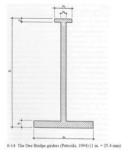
The bridge was deigned by the noted engineer Robert Stephenson. Because cast iron is weaker in tension than in compression, the tension flanges of girders were larger than compression flanges by a ratio of 16:3, following the ratio of material strengths. The Dee Bridge had a relatively long simple span for the day of roughly 29 m (95 ft). The girder cross section is shown in figure 6-14. The bridge was also designed with a relatively low factor of safety of 1.5.
The bridge was completed in September 1846. In May 1847, 125 mm (5 in) of ballast was added on top of the wooden decking, in part to reduce the risk of fire from the sparks of the locomotives. When the first train crossed the bridge after the installation of the ballast, the bridge sank beneath it. The locomotive reached safety, but five cars fell into the river. Five people were killed and 18 were injured.
The most likely cause of failure was a torsional buckling instability to which the bridge girders were predisposed by the compressive loads introduced by the eccentric diagonal tie rods on the girder (Petroski, 1994, p. 90). In effect, the top flange of the girder became a column under the compressive force and buckled out of plane, causing the collapse.
Mianus River Bridge
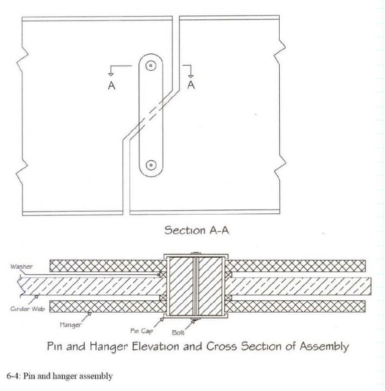
In the late 1950s, a simple span bridge was built over the Mianus River in Cos Cob, Connecticut, as part of Interstate 95 and the Connecticut Turnpike. This bridge design included pin and hanger style connections commonly used at the time. The Mianus River Bridge was a multispan structure carrying more than 100,000 vehicles per day (Levy and Salvadori 1992, p. 138). On the morning of June 28, 1983, at around 1:30 a.m., an eastbound section of the bridge fell into the chilly waters of the river, leaving three people dead and others injured. Each bridge span was 30 m (100 ft) long, three travel lanes wide, with a 53� skew. Each section had a 2.7-m (9-ft) deep plate girder on each side, on top of a 190-mm (7.5-in.) concrete deck topped with 50 mm (2 in.) of asphalt. The mass of the bridge section was approximately 500 tonnes (500 tons). The drop to the tidal flats was 20 m (70 ft) (Feld and Carper 1997, p. 145).
Like the Point Pleasant Bridge, the Mianus River Bridge on the Connecticut Turnpike (I-95) had collapsed after decades of service. The bridge’s skewed simple spans were suspended on pins and hangers. Ten years before the accident, the bridge’s storm drains had been paved over. This paving allowed water, silt, and dirt to drop directly onto the hanger assembly and accelerate corrosion. The end caps that were intended to keep the hangers from slipping off the pins were only 7.5 mm (0.3 in.) thick (Feld and Carper 1997, pp. 145-148). The NTSB report concluded that the collapse of the bridge probably occurred because of “deficiencies in the State of Connecticut’s bridge safety inspection and bridge maintenance program” (NTSB 1983). Many similar bridges were retrofitted to prevent similar collapses (Levy and Salvadori 1992, p. 148).
The key reference for this case is the NTSB (1983) highway accident report Collapse of Suspended Span of Route 95 Highway Bridge over the Mianus River, Greenwich, Connecticut, June 28, 1983. The case is also discussed in Chapter 9 of Levy and Salvadori (1992). This case study is featured in the History Channel’s Modern Marvels Engineering Disasters 8 videotape and DVD.
Link to the NTSB report summary: https://www.ntsb.gov/publictn/1984/HAR8403.htm
History of the Turnpike: www.nycroads.com/roads/ct-turnpike/
Image from US FHWA: http://www.tfhrc.gov/pubrds/summer95/p95su23.htm

Minneapolis I-35W Bridge Collapse
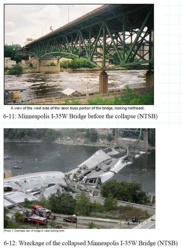
On August 1, 2007, an eight-lane, three-span section of the I-35W Bridge across the Mississippi River in downtown Minneapolis collapsed at approximately 6:00 p.m. It was crowded with rush hour traffic. The final death toll was 13. The bridge was the main north-south route through the city. Figure 6-11 shows the bridge before the collapse. Eyewitness reports suggested that a span at the south end collapsed first and that the failure propagated across the bridge to the other two spans in turn.
Much of the wreckage remained above the water, but about 50 vehicles with their occupants went into the river. At the time, repairs were being made to the bridge deck, guardrails, and lights. Figure 6-12 shows the wreckage of the collapsed bridge.
The National Transportation Safety Board (NTSB) immediately began an investigation, as with most bridge collapses. The investigation team arrived the day after the collapse.
At first glance, this collapse seemed to share some parallels with the Point Pleasant Bridge collapse of 1967 and the Mianus River Bridge failure of 1983. As with the Point Pleasant Bridge, the Minneapolis bridge was 40 years old and collapsed during rush hour with many vehicles on the span. In fact, the Minneapolis bridge was completed just a few months before the Point Pleasant Bridge failure. Both the Point Pleasant and the Minneapolis I-35W Bridge had three spans that all fell together.
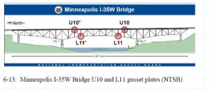
As of summer 2008, the cause of the I-35W Bridge collapse remains under investigation, and the final reports have yet to be written. However, considerable work has been done, and a critical design flaw that may well have been the cause of the collapse has been identified. The U10 and L11 gusset plates, shown in Fig. 6-13, were only about 13 mm (1/2 in.) thick when they should have been 25 mm (1 in.) thick.
At the time of the collapse, the contractor working on the bridge had stockpiled aggregates and heavy construction equipment on the site. Careful reconstruction of the traffic and other loadings by the Federal Highway Administration (FHWA) and others has found that the U10 and L11 gusset plates were considerably overstressed at the time of the collapse (Holt and Hartmann 2008).
The NTSB has posted the FHWA Holt and Hartmann (2008) report and other reports, illustrations, and documents on a website at https://www.ntsb.gov/dockets/Highway/HWY07MH024/default.htm.
Illustrations from Chapter 6 of the book Beyond Failure: Forensic Case Studies for Civil Engineers, Delatte, Norbert J., ASCE Press.
Point Pleasant/Silver Bridge Collapse
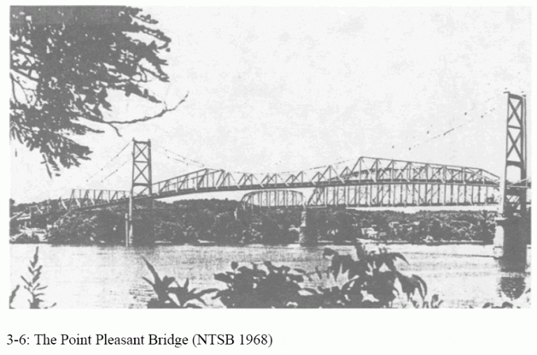
The Silver Bridge provided crossing for US Route 35 over the Ohio River. It connected Columbus, Ohio to Charleston, West Virginia. The bridge crossed between Point Pleasant, West Virginia, and Gallipolis, Ohio. The Silver Bridge not only allowed direct access between the State capitals of Ohio and West Virginia but also provide clearance for the cargo ships that passed through the Ohio River.
On December 15, 1967, the bridge collapsed while handling heavy traffic and killed 46 people. This accident changed the nation’s view of bridges across the country. The government ultimately changed the way bridges were inspected to ensure safety and functionality.
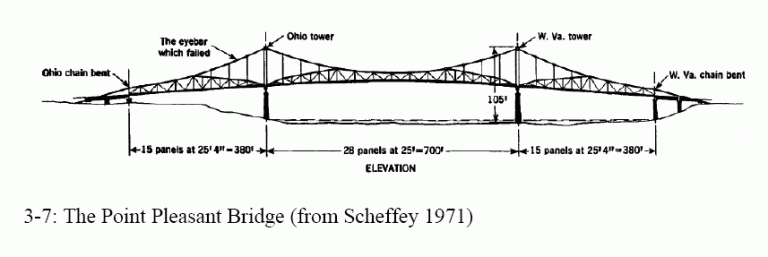
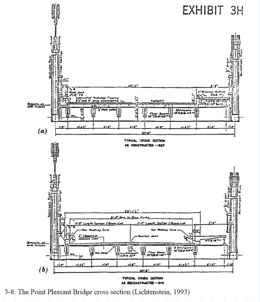
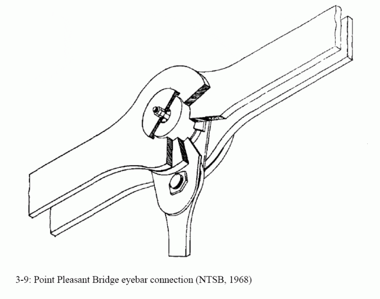
The bridge was completed in 1928. The General Contracting Company of Pittsburgh, Pennsylvania constructed the piers. The American Bridge Company of Pittsburgh built the bridge. It was a unique design due to the use of high-tension eye-bar chains, a unique anchorage system, and the use of rocker towers. The eye-bars were two force bar members with rounded eyes at each end. Because bedrock was at a great depth, piles were octagonal shapes of reinforced concrete. The Anchorage consisted of reinforced concrete troughs that were filled with soil and concrete. This substructure supported the bridge towers, which were joined by dowel rods. This connection allowed for a flexible connection that was designed to shift under different loads on the tower, and as the length of the chains changed due to temperature influences. This type of design was only used in one other bridge in the United States the St. Marys Bridge in West Virginia, also spanning the Ohio River. Although not integral to the Florianopolis truss design concept, the Point Pleasant, and St. Marys bridges introduced the use of high-strength, heat-treated carbon steel eyebars to the U.S.
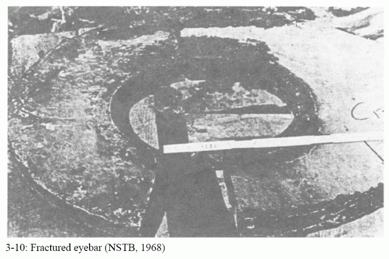
The key lesson from the Point Pleasant Bridge failure is the dangerous interaction between stress concentrations and fatigue. The small built in eyebar flaw, subjected to many load cycles over four decades, led to a sudden and rapid crack propagation through the eyebar.
Another lesson is the value of structural redundancy. The eyebar connection was not redundant. Since it was composed only of two pairs of eyebars, the failure of one eyebar allowed the entire connection to rotate and separate. In contrast, when the Tacoma NarrowsBridge was torn apart by the wind, 500 of 8,700 wires in the suspension cables fractured but the cables as a whole survived. At Florianopolis, Steinman had thickened the heads of the eyebars and used four rather than two bars per link. However, these safety features were not used at Point Pleasant (Wearne 2000 pp. 56-58).
Furthermore, the structure as a whole was also not redundant. The loss of any one structural element would lead to a complete loss of the bridge. With the failure of the Tacoma Narrows Bridge, the towers were bent but stayed up, and the side spans of the bridge remained after the center span fell into the water. In contrast, because the Point Pleasant Bridge towers were supported on rockers at the bottom, they toppled over and all three spans were lost.
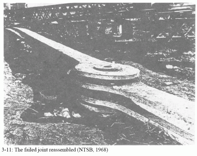
This case is discussed in Chapter 3 of the book Beyond Failure: Forensic Case Studies for Civil Engineers, Delatte, Norbert J., ASCE Press. The National Transportation Safety Board (NTSB) Highway Accident Report Collapse of U.S. 35 Highway Bridge (NTSB 1970) provides a thorough discussion of the failure. Lichtenstein (1993) also provides an excellent review. The case is also discussed by Levy and Salvadori (1992) and Wearne (2000, pp. 45 -58). This case study is featured on the History Channel Modern Marvels Engineering Disasters 4 videotape/DVD.
From West Virginia Archives and History https://www.wvculture.org/HiStory/disasters/silverbridge03.html
Image from US FHWA http://www.tfhrc.gov/pubrds/summer95/p95su23.htm

Illustrations from Chapter 3 of the book Beyond Failure: Forensic Case Studies for Civil Engineers, Delatte, Norbert J., ASCE Press.
The Collapse of the Quebec Bridge, 1907
Introduction
The Quebec Bridge was twenty years in the making, from the founding of the Quebec Bridge Company in 1887 to the bridge’s collapse in 1907. A cantilever bridge was proposed as the most feasible design to bridge the harsh, icy waters of the St. Lawrence River. The bridge collapsed during construction on August 29, 1907, killing eighty-six workers. Only eleven of the workers on the span were recovered alive, and some bodies were never found. A second attempt to bridge the St. Lawrence River was made. However, it also suffered a partial collapse when the middle span fell into the river. Thirteen workers were lost in the second collapse. The bridge was finally completed in 1917, and stands today. A recent review of the history of the bridge and the two collapses was written by Middleton (2001).
Conception, Design, and Construction
The St. Lawrence River was the main channel of trade for Quebec during the summer. During the winter, it filled with ice, and trade was completely cut off until the river iced over and travel was possible again across a dangerous ice bridge. The desire to bridge the St. Lawrence River was fueled by Quebec’s need to be competitive in trade. Montreal already had the Grand Trunk railway system, which passes through it from the west connecting it to Toronto. Quebec was left even farther behind when Montreal began construction in 1854 of the Victoria Bridge, which was completed in 1859, connecting it to western ports. This development quickly established Montreal as Canada’s leading eastern port. Although the need was great, the job of bridging the St. Lawrence would prove to be no easy task (pp. 7 – 8, Middleton, 2001).
The St. Lawrence River was approximately 3.2 km (2 mi.) wide at its narrowest section. Its waters were about 58 m (190 ft) deep at its middle. The velocity of the river reached 13 or 14 kph (8 or 9 mph) at times, and the tides ranged as high as 5 m (18 ft). During the winter, ice became stuck in the narrowing and piled up as high as 15 m (50 ft.) (p. 3, Middleton, 2001).
Interest in building the Quebec Bridge arose as early as 1850. However, the project did not gather momentum until 1887, when a group of businessmen and political leaders came together and formed the Quebec Bridge Committee. Due to the high level of interest in the project, the Canadian Parliament passed an act, which incorporated the committee into the Quebec Bridge Company, with a million-dollar capital and the power to issue bonds (p. 27, Middleton, 2001).
The company now faced the problem of financing the great bridge. Government funding was requested. However, no money could be awarded for the project until the bridge site was selected. With some financial help from the local Quebec legislature, preliminary surveys were made. In 1898, after years of debate, the Chaudiere site was selected from the three recommended sites to be the location of the Quebec Bridge. With a site selected, bridge design proposals poured in (p. 26, Middleton, 2001).
On June 16, 1897, the chief engineer of the Quebec Bridge Company wrote to a friend, who was also the president of the Phoenix Bridge Company (Holgate et al., 1908). In response, the Phoenix Bridge Company sent its chief engineer to meet with the Quebec Bridge Company’s chief engineer at an American Society of Civil Engineers (ASCE) meeting in Quebec in 1897. The Phoenix Bridge Company offered to prepare plans for the bridge free of charge. In return, the Quebec Bridge Company would then be obligated to give the tender for construction of the bridge to the Phoenix Bridge Company. Theodore Cooper, who learned of the Quebec Bridge project at the ASCE meeting, offered his consulting services to the Quebec Bridge Company (pp. 32 – 33, Middleton, 2001). Some of the key players in the construction and failure of the bridge are listed in Table 1.
Table 1. Key Individuals in the Design and Construction of the Quebec Bridge
| Name | Title |
| A. B. Milliken | Bridge superintendent of erection for 1st year of work |
| Benjamin A. Yenser* | General foreman of erection for remainder of project. Worked for Phoenix Bridge Company |
| Arthur H. Birks* | Resident Engineer of Erection |
| Collingwood Schreiber | Chief Engineer for Railways and Canals |
| David Reeves | President of the Phoenix Bridge Company |
| Edward Hoare | Chief Engineer for Quebec Bridge Company |
| E. R. Kinloch | Bridge erection inspector |
| John Sterling Deans | Chief Engineer for Phoenix Bridge Company |
| Norman McLure | Bridge Inspector, Civil Engineering Graduate from Princeton, hired by Cooper |
| Peter L. Szlapka | Chief Designing Engineer for Phoenix Bridge Company |
| Robert C. Douglas | Bridge engineer for Railways and Canals |
| Simon-Napoleon Parent | President of the Quebec Bridge Company |
| C. C. Schneider | Commissioned to review design work on the bridge after the collapse |
| Theodore Cooper | Consulting Engineer |
* Died in the collapse
The chief engineer of the Quebec Bridge Company, Edward Hoare, had never before worked on a bridge longer than about 90 meters (300 feet). The company decided to hire a consulting engineer, and Theodore Cooper was selected from a list of six prominent engineers for the project (Holgate et al., 1908, p. 36, Middleton, 2001). Mr. Cooper was an independent consultant operating out of New York City. He was one of the foremost American bridge builders of his day. To Mr. Cooper, this project would be the crowning achievement to his life’s work.
Petroski (1995) notes Cooper’s strong qualifications for this project. In his long career, he had written an award-winning paper pioneering the use of steel for railway bridges, and had prepared general specifications for iron and steel bridges. His method of accounting for railroad loads on bridge structures became widely used (p. 37, Middleton, 2001).
Tenders were called for on September 6, 1898 and received until March 1, 1899 (Holgate et al., 1908). They were then reviewed by Mr. Cooper. The specifications called for a cantilever structure. The basic configuration of a cantilever bridge is shown in figure 1. However, suspension bridge designs were allowed, providing they came with their own set of specifications. Earlier, noted French engineer Gustave Eiffel had considered the problem and found that a cantilever design would be superior to either a suspension or an arch bridge for the Quebec site (pp. 29 – 30, Middleton, 2001).
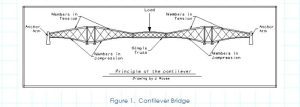
The concept of the cantilever structure was first used in 1867. William Middleton gives a clear definition of a cantilever bridge in his book: “Cantilever bridge: a bridge form based upon the cantilever principal. In its typical form cantilever arms projecting toward the center of the span from main piers are continuous with and counterbalanced by anchor arms extending between the main piers and anchor pier at each end. A simple span suspended between the two cantilever arms completes the structure. The weight of the suspended span and the cantilever arms is counterbalanced by that of the anchor arms and an anchorage embedded in the anchor pier.” (p. 175, Middleton, 2001).
Six tenders were submitted for the superstructure, and two for the substructure. After review, Theodore Cooper stated, “I hereby conclude and report that the cantilever superstructure plan of the Phoenix Bridge Company is the ‘best and cheapest’ plan and proposal submitted to me for examination and report.” (p. 15, Holgate et al., 1908, p. 34, Middleton, 2001).
The Quebec Bridge was the longest cantilever structure ever to be attempted during its day. It would bridge the St Lawrence River approximately 14 km (9 miles) North of Quebec connecting into the Grand Trunk rail line. The cantilever arms would reach a distance of 171.5 m (562.5 ft.). They were to support a suspended span with a length of 205.7 m (675 ft.). It would stand 45.7 m (150 ft.) above the river. The initial design length clear span was 487.7 m (1,600 ft).
However, in May 1900, this span was increased to 548.6 m (1,800 ft.) by Theodore Cooper. He stated that this would eliminate the uncertainty of constructing piers in such deep water, lessen the effects of ice, and shorten the time of construction of the piers. Although there were sound engineering reasons for this change, it was also true that the lengthening of the span would also make Cooper the Chief Engineer for the longest cantilever bridge in the world (Petroski, 1995, p. 46, Middleton, 2001).
The Phoenix Company had been in correspondence with Cooper throughout this process (Holgate et al., 1908). In addition, the Quebec Bridge Company was in favor of the Phoenix Bridge Company to win the tender (Tarkov, 1986). This provides at least an impression that the process was not fair and open, even though, (Holgate et al., 1908) concluded, “As to either party influencing Mr. Cooper or causing him to modify his ideas so as to favour any tender, such a suggestion is, in our opinion, quite out of the question, and we believe that Mr. Cooper made his decisions and gave his opinions with absolute honesty.” (p. 15, Holgate et al., 1908).
Two months later the company awarded contracts to the Phoenix Bridge Company for construction of the superstructure and to the Davis Firm for construction of the substructure. However, the Phoenix Bridge Company refused to sign a contract with the Quebec Bridge Company due to the financial provisions, which left the bridge company open to considerable risk. Financial matters were finally resolved in 1903, when additional funds became available from a government grant. On June 19, 1903, a final contract was entered into between the two companies, and the name of the Quebec Bridge Company was changed to the Quebec Bridge and Railway Company (pp. 45 – 47, Middleton, 2001).
Construction of the bridge officially began on October 2, 1900, after a grand ceremony. The Quebec Bridge Company had enough funds to begin erecting the substructure. The completed piers would stand approximately 8 m (26.5 ft.) above the highest water level. The piers were made of huge granite facing stones with concrete backing. The top 5.8 m (19 ft.) of each pier was made of solid granite. The piers were tapered 1 in 12 (1 in. per foot) until they reached the dimensions of 9.1 m (30 ft.) by 40.5 m (133 ft) at the top. Each pier rested on a concrete filled caisson that was 14.9 m (49 ft) wide, 7.6 m (25 ft.) high, and 45.7 m (150 ft.) long, weighing 16.2 MN (1,600 tons) (pp. 48 – 50, Middleton, 2001).
The main vertical posts of the Quebec Bridge, once complete, would stand 96 m (315 ft.) tall and weigh approximately 3.49 MN (350 tons) (ER, 1907c). The anchor pier towers would withstand a load of 34.8 MN (3,500 tons). The tension eyebars were designed to withstand a maximum stress of 108.5 MPa (15,730 psi) and were about 12.8 m (42 ft) long (ER, 1907a). The floor system was designed to carry a live load of well over 2.79 MN (280 tons) (ER, 1907d). Due to the unprecedented size of this structure, innovative construction methods proved necessary (ER, 1907c). These considerations made the construction of the bridge a slow process.
Under a separate contract with the Quebec Bridge Company, the Phoenix Bridge Company began the construction of the approach spans in 1902 and completed them in 1903. Erection of the superstructure portion of the bridge did not begin until July 22, 1905. The Phoenix Bridge Company agreed to have the structure completed by the last day of the year in 1908. Otherwise, the company would pay $5,000 per month after this deadline to the Quebec Bridge Company until the project was finished (Holgate et al., 1908, Middleton, 2001).
Vents Leading Up to the Collapse
As the bridge was erected, workers and supervisors found noticeable deflections in some of the chords. When the workers tried to rivet the joints between these chords, the pre-drilled holes did not line up. In addition, bends (deflections) were observed in some of the most heavily loaded compression members. Over time, some of the member deflections increased. Some of the major chords with their corresponding deflections, with the dates of measurement, are presented in table 2.
Table 2. Bridge Member Deflections
| Date of Observation | Member | Amount of Deflection | |
| mm | inches | ||
| June 15 | 1.5 � 6.5 | 1/16 to � | |
| June | A3R & A4R | 1.5 � 6.5 | 1/16 to � |
| June | A7R & A8R | 1.5 � 6.5 | 1/16 to � |
| June | A8R & A9R | 1.5 � 6.5 | 1/16 to � |
| June | A8L & A9L | 19 | � |
| August 6 | 7L & 8L | 19 | � |
| August | 8L & 9L | 8 | 5/16 |
| August 20 | 8R | Bent | Bent |
| August | 9R & 10R | ——- | ——- |
| August 23 | 5R & 6R | 13 | � |
| August 27 | A9L | 57 | 2 � |
Deflections were first noticed as early as mid-June, and were reported to Cooper by his on-site inspector, Norman McLure. Compression members had been cambered, so that under load the joints would line up and could be riveted together. However, some of the joints failed to close. Both men presumed that the relatively small deflections had occurred due to a pre-existing condition. They were not alarmed (p. 72, Middleton, 2001).
Subsequent inspections turned up more deflecting chords in August. Again, these were reported to Cooper on the same day that they were discovered. Cooper wired a message back referring to chords 7L and 8L, asking, “How did bend occur in both chords?” The chief engineer of the Phoenix Company replied to Cooper saying that he did not know (pp. 72 – 73, Middleton, 2001).
The chief designing engineer for the Phoenix Company, Peter Szlapka, was certain that the bend was put in the chord ribs at the shop. He later admitted that he never actually saw the chords in question. However, Norman McLure wrote, “One thing I am reasonably sure of, and that is that the bend has occurred since the chord has been under stress, and was not present when the chords were placed.” While this dispute of how the bend occurred in chords, 7L and 8L was going on, McLure reported to Cooper another occurrence of a similar bend in chords 8L and 9L (pp. 73 – 74, Middleton, 2001). The members with these deflections were the lower chords of the truss on either side of the pier – the members with the highest compressive loads under the negative moment across the pier.
A disturbing pattern was emerging. The members under the highest compressive loads were gradually buckling. These were built up with latticing, and as they deflected higher stresses were placed on the latticing as well as the rivets attaching the lattices to the main compression members.
Being dissatisfied with the theories offered by the engineers on site, Cooper developed his own theory. “None of the explanations for the bent chord stand the test of logic. I have evolved another theory, which is a possible if not the probable one. These chords have been hit by those suspended beams used during the erection, while they were being put in place or taken down. Examine if you cannot find evidence of the blow, and make inquiries of the men in charge.” McLure did as he was instructed, and reported back to Cooper that there was no evidence of such an incident (p. 74, Middleton, 2001).
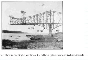
Some of the engineers were unconcerned about the problem, believing that it was nothing serious. Others were still insisting that the bends were the result of a pre-existing condition. The manufacturer guaranteed that all the members had been perfectly straight when they left the yard. Another incident had occurred during the 1905 construction season, when chord A9L was dropped and bent while being handled in the storage yard. The A9L notation refers to the chord located in the anchor arm, within the ninth panel, and on the left or West side of the bridge. It was repaired and placed into the structure. Although at the time the repair was thought to be satisfactory, this member was later found to be the triggering cause of the collapse.
Cooper, although the most experienced, seemed to be the most confused by the problem. He was sixty years old at the time he accepted the position of consulting engineer for the Quebec Bridge project. He also accepted the responsibility of shop inspector of the steel fabrication and erection. His health was poor and because of this, he never visited the site once construction began on the superstructure. His consulting services were based on the information that was reported to him by others in charge. Cooper’s official eyes and ears on the construction site was Norman McLure, a young civil engineer who had been appointed by Cooper himself. Cooper was also very poorly compensated for his work (Petroski, 1995, Middleton, 2001).
McLure continued to argue that the bends in the members had occurred after they were installed. Some of the workers had observed the deflecting chords and were concerned enough to not report to work for a few days. However, when McLure and Cooper disagreed on the cause of the deflections, McLure did not have the confidence to contradict Cooper. Work continued on the bridge. There had already been a three-day strike over working conditions, and the workers who had not agreed with the new terms had left. This greatly reduced the number of workers on the project, and there was concern that a temporary stoppage would cause more workers to leave and delay the project.
After another routine inspection, chord A9L was placed under observation when its initial deflection of 19 mm (��) had increased to 57 mm (2 ��) in less than two weeks. The opposite chord A9R was bent in the same direction. There was growing concern about the deflections. One of the construction foremen decided to halt work on the bridge until matters could be resolved. On August 27, the same day construction was halted; McLure sent a message to Cooper informing him that construction would not resume until he reviewed the matter. The next day, McLure went to New York to seek advice from Cooper (pp. 78 – 79, Middleton, 2001).
The erection foreman that had ordered the work to stop changed his mind, and with reassurance from Edward Hoare, the chief engineer of the Quebec Bridge Company, work began again that day. The only reason given for this decision was in a note from Hoare to Cooper stating, “the moral effect of holding up the work would be very bad on all concerned and might also stop the work for this season on account of losing the men.” Two days later, news of the matter reached the Phoenixville office and the project superiors there met and discussed the problem. They relayed a message back by telephone, saying that it was safe to resume work on the bridge. They had somehow reached the conclusion that the bends in the chords had occurred before they left the yard. The Phoenix Company’s chief engineer had stated that the chord members were carrying “much less than maximum load.”
In the meantime, McLure was meeting with Cooper in New York. Neither of the men was aware that construction had resumed on the bridge. After a brief discussion between the two men on August 29, Cooper wired the Phoenixville office saying, “Add no more load to the bridge until after due consideration of facts. McLure will be over at five o’clock.” Cooper’s reasoning for informing the Phoenixville office rather than directly relaying it to the site, was that he felt that action would be taken faster if the information went to the site through Phoenixville. McLure had assured Cooper that he would wire the information to the site on his way to the Phoenixville office. In his haste to get to his destination, he neglected to send the information.
The message from Cooper reached the Phoenixville office at 1:15 p.m. It was ignored in the absence of the chief engineer. At around 3:00 p.m. Phoenixville’s chief engineer returned to his office. After seeing the message, he arranged for a group meeting as soon as McLure arrived. McLure arrived at roughly 5:15 p.m. and the men discussed the circumstances briefly before deciding to wait until the next morning to decide a course of action (pp. 78 – 80, Middleton, 2001).
Collapse
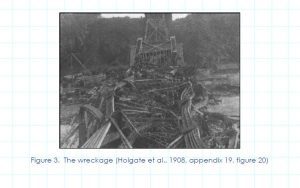
Meanwhile, back at the construction site, at about the same time the decision-makers in Phoenixville were ending their meeting, the Quebec Bridge collapsed at 5:30 p.m. The thunderous roar of the collapse was heard ten km (six miles) away in Quebec (p.80, Middleton, 2001). The entire south half of the bridge, approximately 189 MN (19,000 tons) of steel, fell into the waters of the St. Lawrence within 15 seconds. Eighty-six workers were present on the bridge at the time. Only eleven workers on the span survived.
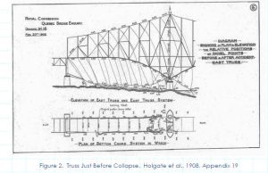
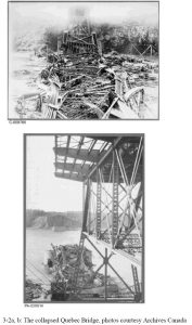
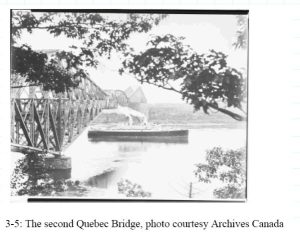
The A9L bottom compression chord, which was already bent, gave way under the increasing weight of the bridge (figure 2). The load transferred to the opposite A9R chord that also buckled. The piers were the only part of the structure that survived. The wreckage is shown in figure 3. Of 38 Caughnawaga Mohawk ironworkers who had left their village to work on the bridge, 33 were killed and two were injured (p. 84, Middleton, 2001).
The Royal Commission Report
The Governor General of Canada formed a Royal Commission, comprised of three civil engineers, whose sole task was to investigate the cause of the collapse. They were Henry Holgate, of Montreal, John George Gale Kerry of Campbellford, Ontario, and John Galbraith of Toronto. Their completed report was a pioneering event in the discipline of forensic engineering, and consisted of over two hundred pages plus twenty-one appendices. As stated by (Middleton 2001, p. 91), “the thoroughness and objectivity of their inquiry and report stand even today as models of their kind.”
The immediate cause of failure was found to be the buckling of compression chords A9L and A9R. The official report attributed the collapse to a number of reasons. Listed below are some of the major findings (pp. 9 – 10, Holgate et al., 1908):
- “The collapse of the Quebec Bridge resulted from the failure of the lower chords in the anchor arm near the main pier. The failure of these chords was due to their defective design.”
- “We do not consider that the specifications for the work were satisfactory or sufficient, the unit stresses in particular being higher than any established by past practice. The specifications were accepted without protest by all interested.”
- “A grave error was made in assuming the dead load for the calculations at too low a value and not afterwards revising this assumption. This error was of sufficient magnitude to have required the condemnation of the bridge, even if the details of the lower chords had been of sufficient strength, because, if the bridge had been completed as designed, the actual stresses would have been considerably greater than those permitted by the specifications. This erroneous assumption was made by Mr. Szlapka and accepted by Mr. Cooper, and tended to hasten the disaster.”
- “The loss of life on August 29, 1907, might have been prevented by the exercise of better judgement on the part of those in responsible charge of the work for the Quebec Bridge and Railway Company and for the Phoenix Bridge Company.”
- “The failure on the part of the Quebec Bridge and Railway Company to appoint an experienced bridge engineer to the position of chief engineer was a mistake. This resulted in a loose and inefficient supervision of all parts of the work on the part of the Quebec Bridge and Railway Company.”
- “The work done by the Phoenix Bridge Company in making the detail drawings and in planning and carrying out the erection, and by the Phoenix Iron Company in fabricating the material was good, and the steel used was of good quality. The serious defects were fundamental errors in design.”
- “The professional knowledge of the present day concerning the action of steel columns under load is not sufficient to enable engineers to economically design such structures as the Quebec bridge. A bridge of the adopted span that will unquestionably be safe can be built, but in the present state of professional knowledge a considerably larger amount of metal would have to be used than might be required if our knowledge were more exact.”
Causes of Failure
The fall of this massive bridge can be traced back to several technical factors. The top and bottom chords for the anchor and cantilever arms of a bridge were typically designed as straight members. This common practice made the fabrication of these members easier. The top chords for the anchor and cantilever arms in the Quebec Bridge were slightly curved, for aesthetic reasons. This added difficulty to the fabrication of such unusually large members. The curvature also increased the secondary stresses on the members, reducing their buckling capacity. According to Engineering Record, “As a rule secondary stresses are much more dangerous in tension that in compression members, which seem to have been the first to give way in the Quebec bridge�”(ER, 1907e).
Another concern during the erection of the bridge was the joints. The ends of all the chords were cambered to allow for the small deflections that were expected to occur when the chords came under their full dead load. These butt splices were bolted to allow for movement. The splices initially touched only at one end, and could not fully transfer their load until they had deflected enough to cause full contact at the splices. At this point, they were permanently riveted in place. The result was to be a rigid joint that transferred loads uniformly across its area to ensure only axial loading. Great care had to be taken while working around these joints until they were riveted (pp. 70 – 72, Middleton, 2001).
Adding to the design problems, Cooper increased the original allowable stresses for the bridge. He allowed 145 MPa (21 ksi) for normal loading and 165 MPa (24 ksi) under extreme loading conditions. These were questioned by the bridge engineer for the Railways and Canals as being unusually high. The new units stresses were accepted anyway based solely on Cooper’s reputation (Holgate, et al., 1908).
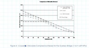
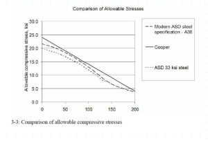
Cooper developed an allowable compressive stress formula (developed in psi) based on the slenderness ratio (l/r) of the member:
Allowable compressive stress = 165 � 0.69 (l/r) MPa = 24,000 � 100 (l/r) psi (1)
Where l = length of compression member,
r = radius of gyration =
I = moment of inertia, and
A = cross-sectional area.
Cooper’s formula is compared to contemporary allowable stresses from the American Institute of Steel Construction (AISC, 1989) as well as the 96.5 MPa (14 ksi) allowable stress adopted for the second bridge (p. 107, Middleton, 2001) in figure 4. AISC curves are shown for both 230 MPa (33 ksi) and 250 MPa (36 ksi) steel. Cooper’s stresses are higher than those in use today by 3.3 to 8.7 % over a range of slenderness ratios from 10 to 100. Given the lower and uncertain quality of the materials available to Cooper, along with the less developed state of knowledge of compression members at that time, Cooper’s formula clearly represents an unsafe practice.
The Quebec Bridge was an enormous structure, and very little was known as to how it would behave mechanically. The Quebec Bridge Company lacked funding to adequately perform testing. Cooper had required extensive tests on the eyebars. The eyebars formed major tension members in the top chords. He did not require the compression members to be tested. Later, Cooper would state the reason for this as being, “There is no machine or method existing by which any such test could be made” (p. 56, Middleton, 2001). However, when the company did finally secure funds for testing, Cooper rejected the idea stating that too much time had been wasted already.
Another oversight was that the stresses were not recalculated once Cooper increased the span from 487.7 m (1,600 ft) to 548.6 m (1,800 ft). The stress calculations were based on the 487.7 m (1,600 ft) span dimension. Once this error had been discovered and brought to Cooper’s attention, he immediately made an estimate of the new stresses that would occur. He found that they would be approximately 7 percent more. Weights were then recalculated from the new information. They were found to be as much as 10 percent in excess of those previously calculated (p. 65, Middleton, 2001). The initial design weight for the bridge was expected to be 276 MN (62 million pounds). The real weight of the bridge was estimated at 325 MN (73 million pounds) (Tarkov, 1986).
In the rush following the final financial arrangements of 1903, the necessity of revising the assumed weights was overlooked both by the engineers of the Phoenix Bridge Company and by those of the Quebec Bridge Company, with the result that the bridge members would have been considerably over-stressed after completion. “This error was sufficient to have condemned the bridge had it not fallen owing to other causes.” (p. 37, Holgate et al., 1908).
Table 3, based on the Royal Commission Report, compares the actual and assumed dead loads. “The difference between these two sets of concentrations indicate a fundamental error in the calculations for the bridge. In a properly computed bridge the assumed dead load concentrations upon which the make-up of the members is based should agree closely with the weight computed from the dimensions in the finished design and with actual weights” (Holgate et al., 1908).
Table 3. Comparison of Assumed and Actual Dead Load
| Element | Assumed Dead Load | Actual Dead Load | Difference | ||
| kN | lb. | kN | lb. | Percent | |
| Half suspended span | 21,538 | 4,842,000 | 25,328 | 5,694,000 | 17.6 |
| Cantilever arm | 58,740 | 13,205,200 | 70,300 | 15,804,000 | 19.7 |
| Anchor arm | 59,240 | 13,317,600 | 77,034 | 17,318,000 | 30.0 |
At the time this error was discovered, a large portion of the fabrication had been completed and a considerable amount of bridge erection was finished. Cooper accepted these heavier loads and stresses, in addition to the already high stresses set for the bridge, as being within acceptable limits. His only other alternatives were to start over, strengthen the bridge in place, or abandon the project.
Procedural and Professional Aspects
Cooper insisted on retaining full control of the project, even at a considerable distance. Schreiber recommended that the governmental agency of Railways and Canals hire a consultant on their behalf. This engineer would, in a sense, be double-checking Cooper’s work and ultimately have the final authority. After finding out this news, Cooper, the Quebec Bridge Company, and the Phoenix Bridge Company immediately objected. In a letter to Edward Hoare, Cooper wrote, “This puts me in the position of a subordinate, which I cannot accept.” (p. 52, Middleton, 2001). Cooper met with Schreiber personally. Following this meeting, Schreiber revised his recommendation to eliminate the need to hire an additional project consultant. The new amended order-in-council to the Railways and Canals gave an unclear definition of just how much authority Cooper would have over the project.
According to Middleton (p. 53, 2001), “While there remained a requirement to submit all plans for the approval of the chief engineer of Railways and Canals, it was treated as a perfunctory formality. When later modifications to the specifications appeared desirable, Cooper made them without reference to the government engineers, and there was no evidence that Schreiber ever questioned a decision made by Cooper or interfered in any way with the work.” This opinion is supported by a statement in a letter from Deans to Cooper. In it he wrote, “The suggested action by Mr. Schreiber would place the business in a much worse condition than it was originally in.” He also wrote, “it is simply being necessary to have Schreiber’s signature as a matter of form.” To further these implications, in a another letter from Deans to Cooper, he wrote, “I have written him again, (Schreiber) and urged him to stop entirely this proposed plan, and explaining that the sole purpose of the order in council was to give you the final authority to settle all details, the government approval being a mere formality, and in this way save time which was so valuable” (Holgate et al., 1908).
No clear chain of command existed. It was assumed that the final authority rested with Theodore Cooper. All concerns were directed towards him, even though, due to illness, he was unable to travel to the job site. There was no one present on the job site that was qualified to oversee this type of work or who was in a position to make a decision. Whenever the need arose, the authorities on site would confer with each other before making any decision. In the few occasions where some decision had been reached, there was hesitation in carrying it out. The authors of the Royal Commission Report wrote, “It was clear that on that day the greatest bridge in the world was being built without there being a single man within reach who by experience, knowledge and ability was competent to deal with the crisis” (Holgate et al., 1908).
Capacity of Compression Members
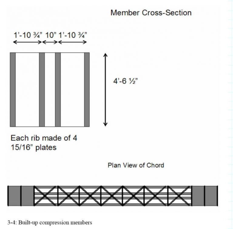
The commission had suspected that the A9L compression chord failed due to improper latticing. Compression tests were performed on one-third scale models of the compression chords in November 1907 and January 1908 to verify this theory. The compression chord members for the Quebec Bridge consisted of four multi-layered ribs (figure 5). They were stiffened by the use of diagonal latticing to make them act as one unit. During testing, the lattice system failed explosively due to shearing of its rivets, immediately followed by buckling of the chord. This confirmed the commission’s findings that the chords were inadequately designed. In Schneider’s opinion, “These members consist of four separate ribs, not particularly well developed as compression members, and their connections to each other are not of sufficient strength to make them act as a unit” (p. 97, Middleton, 2001). Schneider wrote in his report, which was published as an appendix to the Royal Commission Report, “If a column is made up of several shapes or parts, they have to be connected in such a manner that they will act as a unit. In an ideal column each part would take its share of the load and no connection would be required. In practice, however, as stated before, bending will occur before the buckling load is reached, causing shearing strains which have to be transferred through the connections, as latticing, tie plates or cover plates. These connection parts have, therefore, to perform the same function as the web of a girder or the web system of a truss” (Holgate et al., 1908).
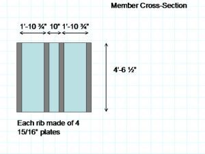
Figure 5: The Built-up Compression Members (1 ft. = 305 mm, 1 in. = 25.4 mm)
This unprecedented large scale testing and studying of compression members and their connections led to major advancements in the field of engineering. Bridge specifications were improved after this collapse (Shepherd and Frost, 1995). Another advancement was the formation of two organizations, the American Institute for Steel Construction in 1921, and the American Association of State Highway and Transportation Officials in 1914. These organizations advanced the field of engineering by providing the means to fund research, which had become too difficult and expensive for fabricating companies to conduct on their own (Roddis, 1993).
Ethical Aspects
Several ethical concerns can be pointed out in this case. The major one is that deformations went unheeded for so long. The engineers on site argued among themselves as to the cause. Although the workers who failed to report to work because of the deformations lacked the technical expertise, they seemed to be the only ones who properly understood what was really happening to the bridge (p. 78, Middleton, 2001). Engineers and others in charge must be open minded to the ideas of the laborers, many of which have years of hands on experience.
Another ethical concern was Cooper’s rejection to having an independent engineer check his work. His decisions were not questioned, even when they seemed to be unusual. An independent consultant may have not allowed the higher than normal design stresses. Some of the other errors such as the underestimated dead loads and the failure to recheck the weight could have been discovered before the bridge collapsed. In conclusion of this thought, “Cooper’s engineering expertise became the sole factor that was relied upon for assuring structural integrity of the bridge.” (Roddis, 1993).
Aftermath
The lives of those involved with the Quebec Bridge, from the designers to the construction workers, were forever changed after the accident. None however, was affected as much as the families of the ones who died and Theodore Cooper. Edward Hoare went to work for the National Transcontinental Railway Commission. John Deans continued to serve as chief engineer of the Phoenix Bridge Company. He eventually became vice president of the company. Szlapka continued his duties as chief designer for the Phoenix Company. Cooper withdrew from practice to live out a lonely retirement. Ironically, he died only two days after the Prince of Wales officially dedicated the completed Quebec Bridge (Middleton, 2001).
The Second Bridge
After the collapse, the government took over the design and construction of the new bridge. This also provided the financial support for the project. The second bridge was substantially heavier than the first. Petroski (1995) compares dimensions of the two bridges, showing the dramatic increase in member sizes. The cross sectional area of the critical compression member for the old bridge had been 543,000 mm2 (842 in.2), whereas that of the new bridge was 1,250,000 mm2 (1,941 in.2) (p. 113, Petroski, 1995, p. 116, Middleton, 2001).
The second attempt to bridge the St. Lawrence was not without problems. The project suffered a second collapse in 1916, when a casting in the lifting apparatus broke, causing the center span to fall into the water. Thirteen workers lost their lives in this accident. The 50 MN (5,000 ton) span sank to the bottom of the river to rest beside the wreckage of the first bridge, which still remains there today. The second bridge was finally completed in 1917 and weighed two and a half times as much as the first one (Tarkov, 1986).
Conclusions
At Quebec, the greatest bridge in the world was under construction in 1907 under severe financial constraints, with inadequate funds provided for either engineering work or the bridge itself. These constraints had delayed engineering analysis and led to adoption of unconservative specifications. When the miscalculation of the dead load was identified, the measures taken to re-analyze the structure were not adequate. On this project, virtually every conflict between safety and economy was resolved in favor of economy. Most of the poor engineering decisions were made by the prominent consulting engineer, Theodore Cooper.
Cooper’s reluctance to travel to the site, based on his poor health, led to confusion about responsibility and site supervision. When skilled ironworkers observed the growing deflections, indicating a gradual collapse of the structure, a confident site supervisor might have realized the gravity of the situation and halted construction. However, the engineers on the site lacked the confidence and the authority to contradict Cooper’s judgments.
The Royal Commission Report, which investigated the collapse and identified the engineering and procedural errors that had lead to it, remains a pioneering document in the field of forensic engineering. The lessons learned from the case had many important impacts on the engineering profession, particularly in Canada and the U.S.
Acknowledgements
Support for this research was provided by the National Science Foundation under the project “Developing Case Studies in Failures and Ethics for Engineering Educators,” project number DUE 0127419.
References
American Institute of Steel Construction (AISC) (1989), Manual of Steel Construction, Allowable Stress Design, Ninth Edition, Chicago, Illinois.
Engineering Record (ER). (1907a). “The Anchor Pier Towers of the Quebec Bridge” (1907), Engineering Record, Vol. 55, January 12, pgs. 34-35.
Engineering Record (ER). (1907b). “Erection Attachments for Bottom Chords and Vertical Posts of the Quebec Bridge,” (1907), The Engineering record, building record and the sanitary engineer. Vol. 55, January 19, 1907.
Engineering Record (ER). (1907c). “Erection of the Main Vertical Posts of Quebec Bridge”, (1907), Engineering Record, Vol. 55, January 26, pgs. 92-94.
Engineering Record (ER). (1907d). “The Quebec Bridge Superstructure Details, Part VIII,” (1907), The Engineering record, building record and the sanitary engineer. August 17, 1907.
Engineering Record (ER). (1907e). “The Cause of the Quebec Bridge Failure”, (1907), Engineering Record, Vol. 56, Sept. 14, pg. 276, Sept. 21, pg. 302.
Holgate, Henry; Derry, John, G. G.; Galbraith, John. (1908). Royal Commission Quebec Bridge Inquiry Report. Sessional Paper No 154. S.E. Dawson printer to the King Ottawa.
Middleton, William D. (2001). Bridge at Quebec. Indiana University Press, Indiana, USA.
Petroski, Henry (1995). Engineers of Dreams: Great Bridge Builders and the Spanning of America, Knopf, New York.
Roddis, W. M. Kim (1993). “Structural failures and engineering ethics.” Journal of Structural Engineering. 119(5), 1539-1555.
Shepherd, Robin and Frost, J. David (1995). Failures in Civil Engineering, Structural, Foundation and Geoenvironmental Case Studies. American Society of Civil Engineers, New York, New York.
Tarkov, J. A. (1986). “A Disaster in the Making.” American Heritage of Invention and Technology, Spring 1986, 10-17.
Illustrations from Chapter 2 of the book Beyond Failure: Forensic Case Studies for Civil Engineers, Delatte, Norbert J., ASCE Press.
Other Quebec Bridge Collapse Web Sites
http://www.civeng.carleton.ca/Exhibits/Quebec_Bridge/intro.html
http://www.mysteriesofcanada.com/Quebec/quebec_bridge_collapse.htm
http://www.civ.toronto.edu/funstuff/disaster/quebec.htm
https://www.structurae.net/en/structures/data/str00479.php
https://helios.physics.uoguelph.ca/summer/scor/articles/scor213.htm
The Collapse of the Schoharie Creek Bridge
Summarized from Storey and Delatte, Lessons from the Collapse of the Schoharie Creek Bridge, Proceedings of the 3rd ASCE Forensics Congress, October 19 – 21, 2003, San Diego, California
Introduction
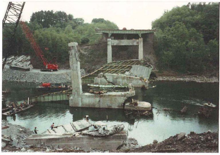
The Schoharie Creek Bridge collapsed on the morning of April 5, 1987, after three decades of service. The collapse of pier three caused two spans to fall into the flooded creek. Five vehicles fell into the river, and ten occupants died.
Bridges across waterways must be designed structurally not only to carry their own weight and traffic loads but also to resist the hydraulic forces imposed by rivers and other bodies of water. Moreover, the construction of the bridge abutments and piers alters the rivers flow, and may lead to new patterns of erosion and deposition. The collapse of the Schoharie Creek Bridge illustrates the importance of designing bridge piers to resist scour. The case also illustrates the importance of the inspection and maintenance of bridges.
Design and Construction
The Schoharie Creek Bridge was one of the several bridges constructed by the New York State Thruway Authority (NYSTA) for a 900 km (559-mile) superhighway across New York State in the early 1950s. The bridge was situated northwest of Albany in the Mohawk Valley (WJE Associates, 1987).
The 1949 edition of the American Association of State Highway Officials (AASHO now the American Association of State Highway and Transportation Officials, AASHTO) Standard Specifications for Highway Bridges was used for the design of the Schoharie Creek Bridge. The preliminary design for the bridge was contracted out to Madigan-Hyland Consulting Engineers (WJE Associates, 1987).
The design firm developed two designs for the crossing of the Schoharie Creek. The preliminary designs were similar except for the lengths of spans, one 183 meters (600 feet) and the other 165 meters (540 feet). Both plans placed two piers on shallow footings in the Schoharie Creek and two piers on the creek banks to support the structure.
The New York State Department of Public Works (DPW), later named the New York State Department of Transportation (NYSDOT), approved the 165 meter (540-foot) bridge for the crossing of the Schoharie Creek. The final design was submitted in January 1952 and consisted of five simply supported spans with nominal lengths of 30.5, 33.5, 36.6, 33.5, and 30.5 meters (100, 110, 120, 110 and 100 feet). Concrete pier frames supported the bridge spans along with abutments at each end (figure 1).
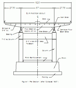
Figure 1. Pier Section
The pier frames were constructed of two slightly tapered columns and tie beams. The columns were fixed within a lightly reinforced plinth, which was positioned on a shallow reinforced spread footing. The spread footing was to be protected by a layer of dry riprap. The superstructure was made up of two longitudinal main girders with transverse floor beams. The skeleton of the 200 mm (eight-inch) thick bridge deck was comprised of steel stringers (WJE Associates, 1987). A plan of the bridge spans is shown in figure 2.
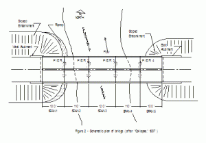
Figure 2. Schematic plan of bridge (after Collapse,1987)
he construction contract for the bridge was awarded to B. Perini and Sons, Inc. on February 11, 1953, and construction began shortly thereafter. Madigan-Hyland Consulting Engineers performed construction inspection for the bridge in conjunction with DPW. The majority of the construction was completed and the bridge was opened to partial traffic during the summer of 1954. The Schoharie Creek Bridge was fully completed soon after October of 1954 (WJE Associates, 1987). Nearly a year later, the bridge successfully survived a 100 year flood, but the damage from the October 16, 1955 flood may have had a bearing on the collapse three decades later (NTSB, 1988).
The as-built plans did not reflect the true condition of the bridge. They showed that sheet piling had been left in place to protect the piers. However, it had been removed after construction (WJE Associates, 1987, NTSB, 1988).
Pier Modifications
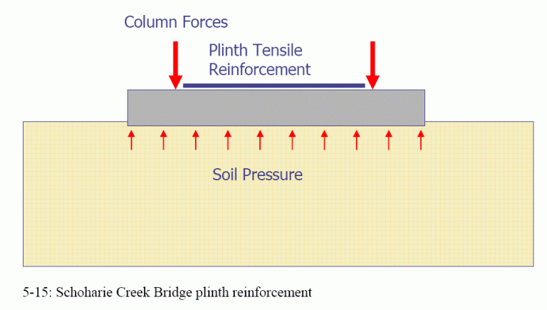
Shortly after construction was completed, in the spring and summer of 1955, the Schoharie Creek Bridge pier plinths (shown in figure 1) began to form vertical cracks. The cracks ranged from 3 to 5 mm (1/8 to 3/16 inches) in width and the locations of the cracks varied from pier to pier (WJE Associates, 1987). The cracks occurred due to the high tensile stresses in the concrete plinth. The plinth could not resist the bending stresses between the two columns. The original designs called for reinforcement to be placed in the bottom portion of the plinth only since designers had confidence that the concrete in tension could resist the bending stresses without reinforcement.
It was later determined that the upper portion of the pier plinths had a tensile stress of 1.4 MPa (200 psi) and there should have been more than 39,000 square mm upwards of 60 square inches of steel in the upper face of the plinth (WJE Associates, 1987). In 1957, plinth reinforcement was added to each of the four piers to correct the problem of vertical cracking.
The plinth may be seen as an upside down uniformly loaded beam, with the soil bearing pressure providing the uniform loading and the two columns acting as supports. It becomes obvious that the top of the plinth represents the tension face of the beam and requires reinforcement. However, to be properly anchored the tension reinforcement must be extended past the supports in this case, into the columns (NTSB, 1988). Obviously, this was not done, and it would have been difficult to extend the reinforcement through the columns without replacing the columns. Ironically, because the added plinth reinforcement was not adequately anchored, it may have contributed to the brittle and sudden nature of the subsequent collapse, by supporting the plinth until most of it had been undermined (WJE Associates, 1987, Thornton-Tomasetti, P. C., 1987).
There were several other problems that occurred shortly after the completion of the bridge. Inspectors noticed that the expansion bearings were out-of-plumb, roadway approach slabs had settled, roadway drainage was poor, and the supporting material for west embankment dry stone pavement was deficient. All of the problems mentioned and other minor problems were corrected by fall of 1957 (WJE Associates, 1987).
The Collapse
The Schoharie Creek Bridge collapsed on the morning of April 5, 1987, during the spring flood (Boorstin, 1987, Thornton et al., 1988). Rainfall totaling 150 mm (6 inches) combined with snowmelt to produce an estimated 50-year flood (WJE Associates, 1987).
The collapse was initiated by the toppling of pier three, which caused the progressive collapse of spans three and four into the flooded creek. The piers and spans are shown in Figure 2. One car and one tractor-semitrailer were on the bridge when it collapsed. Before the road could be blocked off, three more cars fell into the gap. The drivers of the other vehicles were probably too close to the bridge to stop in time when it fell. Over the next three weeks, nine bodies were recovered. One was never found. (NTSB, 1988).
Pier two and span two fell ninety minutes after span three dropped, and pier one and span one shifted two hours after that (Thornton-Tomasetti, P. C., 1987). The NTSB suggested that pier two collapsed because the wreckage of pier three and the two spans partially blocked the river, redirecting the water to pier two and increasing the stream velocity (NTSB, 1988). The missing span and the floodwaters may be seen at the following websites:
| Scour Critical Bridges (2002) https://www.nationalbridgeinventory.com/scour_critical_bridges.htm> |
| Hudson International – includes an animation of the collapse of the second span https://members.aol.com/higrp/bridge.htm |
| MRCE website – Schoharie Creek Thruway Bridge (2002) https://www.mrce.com/pages/projects/1987-3.shtml |
Six days later, a large section of the Mill Point Bridge located about 5 km (3 miles) upstream of the Schoharie Creek Bridge collapsed. Fortunately, the bridge had been closed since the flood because NYSDOT feared that its foundation had also been eroded (WJE Associates, 1987).
Causes of Failure
Two teams investigated the Schoharie Creek Bridge failure Wiss, Janney, Elstner (WJE) Associates, Inc. with Mueser Rutledge Consulting Engineers investigated for the NYSTA, and Thornton-Tomasetti, P.C. investigated for the New York State Disaster Preparedness Commission. The teams cooperated, and the chief role of Thornton-Tomasetti, P.C. was to review WJEs work. A number of other firms assisted in the investigation (Bridge Collapse @ 2002, Schoharie Creek Thruway Bridge @ 2002). A cofferdam was constructed around the failed piers and the site was dewatered and excavated, both to aid the investigation and the construction of the replacement bridge (WJE Associates, 1987).
Each of the teams prepared a report as to the cause of the failure, and they similarly concluded that the collapse of the Schoharie Creek Bridge was due to the extensive scour under pier three. Scour is defined as the removal of sediment from a streambed caused by the erosive action of flowing water (Palmer and Turkiyyah, 1999). The vulnerability of scouring under pier three was affected by four important factors (Thornton-Tomasetti, P. C., 1987):
- The shallow footings used, bearing on soil, could be undermined.Therefore the depth of which the footings was not enough to take them below the probable limit of sour.
- The foundation of pier 3 was bearing on the erodable soil. Layers of gravel, sand, and silt, interbedded with folded and tilted till allowed high-velocity floodwaters to penetrate the bearing stratum.
- The as-built footing excavations and backfill could not resist scour. The area left around the footing due to excavation was backfilled with erodable soil and topped off with dry riprap, in turn rather than being backfilled with riprap stone to the entire depth of the excavation as design plans specified.
- Riprap protection, inspection, and maintenance were inadequate.
The process of scouring under the piers began shortly after the bridge was built. In 1955, the bridge footings experienced floodwater flows unanticipated in the design of the bridge, a 100-year flood, and it is believed that the majority of the scouring energy was dissipated into moving the original riprap layer from around the footings. Once the backfill had been exposed, the years of peak flows removed the backfill material, and the backfill , in turn, as replaced by sediment settling into the scoured holes (WJE Associates, 1987).
The 1955 flood had an estimated flow of 2.17 million liters per second (76,500 cfs). The 1987 flood had an estimated flow of 1.8 million liters per second (63,000 cfs) and an estimated velocity of 4.6 meters per second (15 fps). However, after the 1955 flood, berms were constructed upstream, and the velocity at the bridge may have been the same as the 1955 flood. Furthermore, the riprap placed at construction had probably been washed away during the 1955 flood and had not been replaced (WJE Associates, 1987).
This process continued until so much material was removed that there was a loss of support capacity (Shepherd and Frost, 1995). The upstream end of pier 3 fell into a scour hole approximately 3 meters (9 feet) deep (NTSB, 1988). It was estimated that approximately 7.5 to 9 meters (25 to 30 feet) of the pier was undermined (WJE Associates, 1987).
The damage due to scour is shown at the Hudson International website (https://members.aol.com/higrp/bridge.htm). The bridge design originally called for leaving the sheet piles (which were used to keep water out of the excavation area during construction) around the piers (Levy and Salvadori 1992). The specified riprap would then fill the area left between the pier footings and sheeting.
Unfortunately, the sheet piles were not left in place. Possibly, they could have prevented the scour altogether. Levy and Salvadori note (p. 146) that in the contract issued in 1980 for maintenance work, all reference to new stone riprap had been deleted by a nonengineer state employee who decided, after viewing the site from shore, that it was unnecessary. The NTSB also noted this incident (NTSB, 1988).
The riprap was also too light. The specification called for riprap with 50 % of the stones heavier than 1.3 kN (300 pounds) and the remainder between 0.44 and 1.3 kN (100 to 300 pounds). However, the investigators found that riprap weights of 4.4 to 6.7 kN (1,000 to 1,500 pounds) should have been specified (WJE Associates, 1987).
Although the main cause of the bridge failure was scour, there were several other items considered during the investigation of the collapse. These items include the design of the superstructure, quality of materials and construction, inspection and maintenance of superstructure, inspection, and maintenance of piers above streambed, and inspections performed using the guidelines available at the time of inspections. These items did not contribute to the collapse of the Schoharie Creek Bridge (Thornton-Tomasetti, P. C., 1987).
Thornton-Tomasetti found six items that aggravated the tendency for scour (pp. 3-5, Thornton-Tomasetti, P. C., 1987):
- The flood was greater than that anticipated by the designers and followed the 1955 flood and others that had disturbed the riprap.
- A curve in the river upstream of the bridge directed a higher-velocity flow toward pier 3.
- Drift material caught against the piers directed water downward at the base of pier 3.
- Berms built in 1963 directed floodwaters under the bridge.
- An embankment west of the creek channel increased flood velocities.
- The Mohawk River dam downstream was set for winter conditions and was 3 meters (10 feet) lower than in the 1955 flood, increasing the hydraulic gradient.
Furthermore, Thornton-Tomasetti found a number of other factors that contributed to the severity of the collapse (pp. 5-6, Thornton-Tomasetti, P. C., 1987):
- The bridge bearings allowed the spans to lift or slide off of the concrete piers.
- The simple spans were not redundant.
- The lightly reinforced concrete piers did not have enough ductility to permit frame action.
- The plinth reinforcement stopped the hinge action of the plinth cracks. Therefore, instead of dropping slowly into the scour hole, the plinth cracked suddenly.
The first two elements were common practice when the bridge was designed in the 1950s.
The National Transportation Safety Board conducted its own investigation and concluded that the probable cause of the accident was a failure to maintain riprap. As contributing factors, they pointed to ambiguous construction plans and specifications, an inadequate NYSTA bridge inspection program, and inadequate oversight by the NYSDOT and FHWA (NTSB, 1988).
Scour and Countermeasures
Scour removes material through three mechanisms (Thornton et al., 1988, Palmer and Turkiyyah, 1999). These are:
- Long term aggredation or degradation, the change in channel bottom elevation that occurs through normal erosion and deposition of material in the river bed. Clearly, the degradation is of concern from a bridge safety standpoint.
- Contraction scour when the stream width is narrowed by natural processes or bridge abutment and pier construction. By the continuity equation Q = Av (where Q = flowrate, A = cross-sectional area, and v = velocity), if the channel cross-sectional area decreases then the velocity must increase, resulting in an additional lowering of the channel bottom elevation.
- Local scour occurs when the flow is obstructed by a pier or abutment placed in the floodplain. Vortexes that form at the pier or abutment remove stream bed material. (p. 62, Huber, 1991).
Clearly, at a bridge pier, all three processes occur and are additive. Because the last two mechanisms occur only after the bridge has been constructed, the extent of potential scour may be difficult to estimate in advance.
Scour may be countered by riprap, by supporting piers on piles, my providing cofferdams around piers, and through other measures. The key is an adequate prediction of the hydraulic forces that occur during powerful floods. The analysis should also include the effects of potential land use changes upstream, such as increases in runoff from development and associated paving.
Lessons Learned
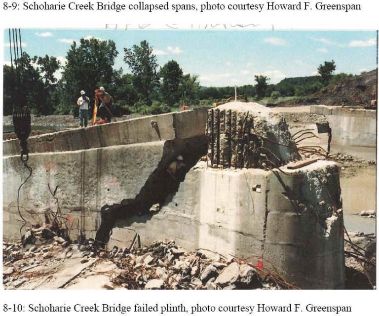
The NTSB suggested a number of ways that the disaster could have been prevented, or that the loss of life could have been reduced. The thruway bridge, like other bridges on the Schoharie Creek, could have been supported on piles, which would have resisted scour. The AASHO 1949 provisions were unclear on whether piles were required for this bridge. In the absence of the piles, leaving the sheet piling in place and providing enough riprap would have helped protect the pier. However, the quantity estimates provided to the contractor by the design engineer did not have enough sheet piling or riprap for pier protection. The use of continuous spans, rather than simple spans, would have provided redundancy once pier three failed, and perhaps allowed for the redistribution of forces between the spans. Also, the plinth reinforcement added after the bridge construction was not anchored in the columns (NTSB, 1988). The reinforcement does not cross the crack in the plinth of pier 3, shown in figure 7.
However, the key lesson pointed out by the NTSB was operational, not technical. It is important for bridge owners to identify the critical features that can lead to the collapse of a bridge and to ensure that those critical features are inspected frequently and adequately (NTSB, 1988).
Technical Aspects. The WJE Associates report notes that bridges must be designed for hydraulic, geotechnical, and structural effects. Of the three, only the geotechnical design, relying on the support strength of the glacial till, was satisfactory (WJE Associates, 1987).
Bridge inspections play a major role in evaluating the superstructure and substructure for deterioration to determine if maintenance is required. Bridge inspections in New York State were required on an annual/biannual basis. The state also required diver inspections of the underwater structures every five years (Levy and Salvadori, 1992).
Although the Schoharie Creek Bridge had been inspected annually or biennially since 1968, an underwater inspection of the piers footings had never been performed. The bridge was scheduled for an underwater inspection in 1987, but the bridge collapsed before the inspection took place (NTSB, 1988).
The Thornton-Tomasetti report notes where riprap is used to prevent scour, inspection and restoration of protective riprap should be performed after every significant flood to avoid progressive damage, and the replacement stones used should be heavier than those which were observed to shift. (p. 20, Thornton-Tomasetti, 1987).
Due to the collapse of the Schoharie Creek Bridge and other bridges failing in a similar manner, bridge inspectors were further trained to recognize scour potential by examining and comparing any changes in the conditions from previous inspections (Huber, 1991). Scouring failures also sparked the much-needed research for detecting scour potential.
The Catalog And Expert Evaluation of Scour Risk And River Stability (CAESAR) system was developed by the University of Washington for evaluating scour through computer technology and for aiding bridge inspectors during the assessment process. The report documenting the program discusses the necessity of identifying screamers,those indicators of imminent collapse that require an agency to close a bridge (Palmer and Turkiyyah, 1999).
Educational Aspects. The bridge failures of the past demonstrate how important bridge inspection is for management and safety of the transportation network. The failures also emphasize how important it is to design footings deep enough to avoid loss of support capacity due to scour (Shepherd, 1995).
Changes to Engineering and Management Practices
When the bridge was built, the tools of the day were not adequate for predicting scour. While the bridge was in service, the inspection procedures used were not sufficient to detect the scour. Since the collapse of the Schoharie Creek Bridge, important advances have been made. A study conducted in 1989 revealed that 494 bridges failed during the years 1951 and 1988 as a result of hydraulic conditions, primarily due to scouring (Huber, 1991).
Summary and Conclusions
The collapse of the Schoharie Creek Bridge was an important event in the development of bridge design and inspection procedures. It is important to accurately predict the effects of scouring, and to design bridges to resist those effects. Lessons learned to include:
- Proper selection of a critical storm for the design of bridges crossing water.
- The need for regular inspections of the superstructure, substructure, and underwater features of the bridge.
- The importance of adequate erosion protection around piers and abutments susceptible to scour.
Print References:
Boorstin, Robert O. (1987). Bridge Collapses on the Thruway, Trapping Vehicles, Volume CXXXVI, No. 47,101, The New York Times, April 6, 1987.
Huber, Frank. (1991). Update: Bridge Scour. Civil Engineering, ASCE, Vol. 61, No. 9, pp 62-63, September 1991.
Levy, Matthys and Salvadori, Mario (1992). Why Buildings Fall Down. W.W. Norton and Company, New York, New York.
National Transportation Safety Board (NTSB). (1988). Collapse of New York Thruway (1-90) Bridge over the Schoharie Creek, near Amsterdam, New York, April 5, 1987. Highway Accident Report: NTSB/HAR-88/02, Washington, D.C.
Palmer, R., and Turkiyyah, G. (1999). CAESAR: An Expert System for Evaluation of Scour and Stream Stability.National Cooperative Highway Research Program (NCHRP) Report 426, Washington D. C
Shepherd, Robin, and Frost, J. David (1995). Failures in Civil Engineering: Structural, Foundation and Geoenvironmental Case Studies. American Society of Civil Engineers, New York, New York.
Thornton, C. H., Tomasetti, R. L., and Joseph, L. M. (1988). Lessons From Schoharie Creek, Civil Engineering, Vol. 58, No.5, pp. 46-49, May 1988.
Thornton-Tomasetti, P. C. (1987) Overview Report Investigation of the New York State Thruway Schoharie Creek Bridge Collapse. Prepared for: New York State Disaster Preparedness Commission, December.
Wiss, Janney, Elstner Associates, Inc., and Mueser Rutledge Consulting Engineers (1987) Collapse of Thruway Bridge at Schoharie Creek, Final Report, Prepared for: New York State Thruway Authority, November.
Web References:
Bridge Collapse (2002). <https://members.aol.com/higrp/bridge.htm>
Schoharie Creek Thruway Bridge (2002)
<https://www.mrce.com/pages/projects/1987-3.shtml>
Scour at Schoharie Creek at Interstate 90 (west pier) (2002) <https://ny.water.usgs.gov/projects/scour/fig5.html>
Scour Critical Bridges (2002) <https://www.nationalbridgeinventory.com/scour_critical_bridges.htm>
Ten Years Since Major Bridge Collapse (1997) <https://ny.usgs.gov/projects/scour/>
Illustrations from Chapters 5 and 8 of the book Beyond Failure: Forensic Case Studies for Civil Engineers, Delatte, Norbert J., ASCE Press.
