Building Failure Cases
2000 Commonwealth Avenue, Boston
An investigation into the collapse of a 17-story concrete high-rise under construction at 2000 Commonwealth Avenue disclosed a number of irregularities and deficiencies, including, among others:
- Lack of proper building permit
- Insufficient concrete strength
- Insufficient length of rebars
- Lack of proper field inspection
- Various structural design deficiencies
- Improper formwork
- Premature removal of formwork
- Inadequate placement of rebars
- Lack of construction control (Kaminetzky 1991)
Four workers were killed and twenty injured. Fortunately, the collapse occurred slowly enough for many of the workers to escape. The collapse occurred on January 25, and low temperatures had certainly retarded strength gain. Cores showed concrete compressive strengths as low as 700 psi (Kaminetzky 1991, Feld and Carper 1997).
Complete case study by Suzanne King:
On January 25, 1971, two-thirds of a 16-story apartment building collapsed while under construction at 2000 Commonwealth Avenue, Boston, MA. Four workers died after a failure on the roof instigated a domino-like collapse all the way to the basement, where the men were found. Fortunately, the collapse took a long enough time for most of the workers to run to safety. This paper investigates the numerous causes and lessons learned of this structural failure.
Introduction
Studying structural failure case studies is a way of studying the history of the engineering profession. Typical calculations for design are based on predicting and avoiding failure. The factor of safety is used to avoid failures, but knowledge of past failures will better equip an engineer to steer clear of future failures. It is not only important to know what caused the failure, but also to understand how it occurred and how to avoid the problem in the future.
In the collapse at 2000 Commonwealth Avenue, Boston, Massachusetts on January 25, 1971, punching shear failure is believed to have triggered the collapse of two-thirds of the 16-story concrete building during construction. But an investigation called for by the mayor proved that there were many flaws in the design of the apartment building. It is important to remind engineers of past failures, such as this one so that history does not repeat itself.
Design and Construction
The high-rise apartment building was made of cast-in-place reinforced concrete flat slab construction with a central elevator shaft. This style of construction is popular for multi-story buildings because it requires a minimum slab thickness and reduces the overall height of the building (Feld and Carper 1997). 2000 Commonwealth Ave. was designed to be sixteen stories with a mechanical room above a five-foot crawl space on the roof. The structure also had two levels of underground parking. A swimming pool, ancillary spaces, and one apartment were located on the first floor and one hundred thirty-two apartments were on the second through sixteenth floors. Originally these apartments were to be rented, but the owners later decided to market them as condominiums.
Construction began on the site late in the fall of 1969. Excavation had been partially started a few years earlier. Most of the work was subcontracted to area specialists. Only one representative from the General Contractor was on site during construction. At the time of the collapse, construction was nearing completion. Brickwork was completed up to the sixteenth floor and the building was mostly enclosed from the second to fifteenth floors. Plumbing, heating and ventilating systems were being installed throughout various parts of the building. Work on interior apartment walls had also started on the lower floors. A temporary construction elevator was located at the south edge of the building to aid in transporting equipment to the different floors. It is estimated that one hundred men were working in or around the building at the time of failure (Granger et al. 1971).
Collapse
After interviewing many eyewitnesses, the mayors investigating commission concluded that the failure took place in three phases. These phases were punching shear failure in the main roof at column E5, a collapse of the roof slab, and, finally, the general collapse.
Phase 1: Punching Shear Failure in the Main Roof at Column E5
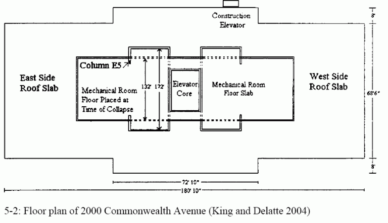
At about ten in the morning, concrete was being placed in the mechanical room floor slab, wall, wall beams, and brackets. Placement started at the west edge and proceeded east. Later in the afternoon, at about three o’clock, most of the workers went down to the south side roof for a coffee break. Only two concrete finishers, Mr. Daniel Niro and Mr. Joseph Oliva, remained on the pouring level near line 4-1/2. Shortly after the coffee break, the two men felt a drop in the mechanical room floor of about one inch at first and then another two or three inches a few seconds later. The labor foreman, Mr. Anthony Paolini, was directing the crane carrying the next bucket of concrete. He instructed the operator to “hold the bucket” and went down to the sixteenth floor by way of a ladder in the east stairway. That is when the punching shear was noticed around column E5. The carpenter foreman, Mr. Antonio M. Fantasia, was also in the area and immediately yelled a warning to the men working on the sixteenth floor and roof of a possible roof collapse. The slab had dropped five or six inches around the column and there was a crack in the bottom of the slab extending from column E5 toward column D8. Column E5 is located directly below where the concrete was being placed for the mechanical room floor slab on the east side of the building as shown in the following figure (Granger et al. 1971).
Phase 2: Collapse of the Roof Slab
After hearing Mr. Fantasia’s warning, most of the workers in the area of column E5 managed to run to an east balcony and stay there until after the roof slab collapse. Eyewitness testimony concluded that the collapse happened fairly quickly. The roof slab began to sag in the shape of a belly and reinforcing steel started sticking out from the mechanical room floor slab. Soon everything started to shake and the east half of the roof slab collapsed onto the sixteenth floor. Then it stopped, giving the workers a chance to run down the stairs to the ground. At the time of failure, the Structural Subcontractor was placing reinforcing steel for the stairs on the fourteenth and fifteenth floors on the east side of the building. So when the workers were making their way from the roof and floors above, most of them crossed over to the west side of the building when they reached the fifteenth floor. (Granger et al. 1971)
Phase 3: General Collapse
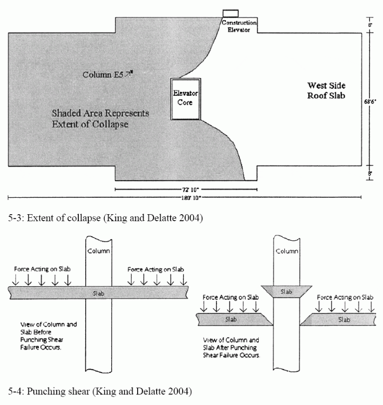
After the roof collapsed, the roof settled and most of the stranded workers could be rescued using the crane and construction elevator. However, about twenty minutes after the roof failed, the east side of the structure began to collapse. A resident of 1959 Commonwealth Ave. described the collapse as a domino effect (or progressive collapse). The weight of the collapsed roof caused the sixteenth floor to collapse onto the fifteenth floor, which then collapsed on the fourteenth floor, and so on to the ground (Litle 1972). At first, the different floors were distinguishable, but later dust and debris made it difficult to discriminate between the various floors. When the dust finally settled, two-thirds of the building had collapsed. The east side and areas on either side of the elevator shaft were gone. Four workers were killed during the collapse and thirty workers suffered injuries (Granger et al. 1971).
The extent of the collapse is shown in the photographs in APPENDIX B. The first picture is from the February 4, 1971, issue of EngineeringNews-Recordd. This picture shows the floor slabs hanging from individual floors. Only the west side of the building remains standing. The next photograph is a close-up of the collapse. It shows the exposed elevator shaft. The building collapsed around the interior elevator.
Causes of Failure
A week after the collapse, Engineering News Record reported that there were three possible causes of structural failure under investigation: formwork for the penthouse floor slab collapsed onto the roof, a heavy piece of equipment fell from a crane and started the progressive collapse or concrete placed during previous cold days had failed (ENR, February 4, 1971). However, after an extensive investigation, the mayor’s commission concluded that there were many design and construction flaws that attributed to the collapse. The committee determined that punching shear failure at column E5 triggered the initial collapse. This type of failure is caused by unbalanced moments transferred between the column and flat-plate (Megally and Ghali 2000) and was a result of non-conformities to the design documents. The major areas that construction did not follow the design were shoring and concrete strength. Inadequate sharing under the roof slab on the east side of the building made it impossible for the roof to hold the freshly placed concrete for the mechanical room floor slab, construction equipment and two boilers that were stored on that side of the building. Also, the concrete strength of the roof slab was well below three thousand pounds per square inch as specified in the design. However, there were many other factors, design and procedural, that contributed to the collapse (Granger et al. 1971).
Design Concerns
The design concerns that contributed to the collapse include insufficient length and placement of rebar and various structural design deficiencies. All of the reinforcing steel used was designed to be billet steel, however, a large amount of rail steel was found in columns and slabs on the lower floors. The major difference between rail and billet steel (as described in the Commission’s report) is the ultimate elongation. The average ultimate elongation for rail steel used on the project was just over ten and a half inches as opposed to a little over fifteen and a quarter inches for the billet steel. This variance would effect how the floor slabs reacted to tension forces. Also, the steel was delivered by the supplier in bundles with marks on the steel indicating what the steel was intended for. However, some of the marks used were the same as the marks on the design plans, yet meant something different. For example, the supplier gave marks for number four bars at the south edge of the slab which was identical to marks given on the Engineers placing drawings for top slab bars over column E5 (Granger et al. 1971). There were also design errors in the reinforcement. Some of the bars did not extend long enough into the columns as required by code and placement of bars in some of the slabs was not sufficient to meet the American Concrete Institutes (ACI) code at the time. There was also inadequate design around columns. ACI requires that at least twenty-five percent of the negative slab reinforcement in each column strip pass over the column within a distance of “d” on either side of the column face (Granger et al. 1971). This requirement was not fulfilled.
Procedural Concerns
There were many procedural concerns in the construction of 2000 Commonwealth Ave. Nearly every step of construction was flawed (Kaminetzky 1991). Some of the major concerns include lack of proper building permit and field inspection, premature removal of formwork, and lack of construction control.
The investigating committee determined that if the construction had had a proper building permit and followed codes, then the failure could have been avoided. Since there were numerous problems that all aided to the collapse, deciding whom to hold responsible for the collapse became a difficult feat. Ownership changed hands many times and most jobs were subcontracted. Some of the transactions that took place with Bostons Building Department are listed in the table below (Granger et al. 1971). There was confusion surrounding the project from the start.
Construction did not follow the Structural Engineers specifications for shoring or formwork. Before removal of shores and forms, the concrete must first reach seventy percent of its designated twenty-eight-day strength. It was the commission’s opinion that despite seven-day cylinder tests that said otherwise, the average strength of the concrete in the roof slab was only nineteen hundred pounds per square inch after at least forty-seven days, not the required twenty-one hundred pounds per square inch for removal or the specified three thousand pounds per square inch required after twenty-eight days. There was no inspection or cylinder testing done for the east side of the building, so removal of formwork was based on values obtained from the west side of the building. Furthermore, adequate shoring under the roof slab below the freshly place mechanical room floor slab was not used (Granger et al. 1971).
Finally, there was very little construction control on the site. There was no architectural or engineering inspection of the project and the inspection done by the city of Boston was inadequate. The design plans specifically stated that certain aspects of the project needed to be approved by an architect, yet no architect or engineer was consulted. The Affidavit Engineer and Licensed Builder were also nowhere to be found. Instead, construction was based on arrangements made by the subcontractors. As mentioned before, there was only one representative from the General Contractor and this man was not a licensed builder. He did not direct, supervise or inspect any of the work done by the subcontractors (Granger et al. 1971).
Similarities to Other Failures
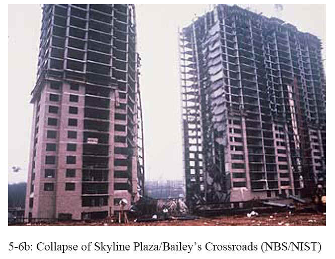
The progressive collapse of 2000 Commonwealth Ave. was similar to the structural failures of buildings in Bailey’s Crossroads and Harbour Cay. On March 2, 1973, the Skyline Plaza in Baileys Crossroads, Virginia collapsed while under construction. Like 2000 Commonwealth Ave., premature removal of shoring and insufficient concrete strength were the causes of failure (Woodward et al. 1983). The collapse of the flat-plate Harbour Cay condominium building in Cocoa Beach, Florida on March 27, 1981, was caused by punching shear failure triggered a progressive collapse (Lew et al.1983), much like 2000 Commonwealth Ave. Investigations following the three collapses concluded that both design and construction errors contributed to the cause of the collapse. All three failures could have been avoided if better inspections of materials and construction details were conducted.
| Event Table for Construction of 2000 Commonwealth Ave. Apartment Building | |
| Date | Action |
| November 3, 1964 | First building permit application was filed for a seven-story, eighty-nine apartment building. Bartholomew W. Consentino is listed as the owner and S. S. Eisenberg is listed as the architect. The permit was first refused because building exceeded allowable building height. A later appeal granted the permit on December 24, 1964. |
| May 24, 1965 | Letter filed by W. J. Lamborghini of La Mont Corporation stated that construction of the building had started. Records show excavation was started and the lot was fenced. |
| August 16, 1967 | Notice was given to Mr. Consentino by the Building Department that his permit has lapsed due to unreasonable delay in completing the building. |
| November 20, 1967 | Mr. Consentino filed a new building permit for a fourteen story, eighty-five apartment luxury building, naming George Garfinkle architect. However, the permit was not signed by “the person who is to perform or take charge of the work covered by the permit” as specified by codes. Therefore, the permit was not issued. The application was then deemed abandoned because there was no permit issued within six months of application. |
| July 3, 1968 | A zoning change for the property was obtained by Mr. Harold Katz. |
| December 23, 1968 | Wilfred Fink of Toronto, Canada; Morris Feinstein and Theodore Hurwitz, both of Montreal,Canada; and Arthur Haffer, Bartholomew W. Consentino, Harold Katz, Stanley H. Rudman, and Lewis G. Pollock, all of Massachusetts, are named owners of the property at 2000 Commonwealth Ave. |
| July 7, 1969 | A permit was issued for a sixteen-story reinforced concrete building designed by the architectural firm of Webb, Zerafa and Menkes of West Toronto, Canada. However, Massachusetts state laws require permits to bear the seal of a registered architect or registered professional engineer from Massachusetts and the architectural firm of Webb, Zerafa, and Menkes does not have any principal or employees in Massachusetts. |
| August 1, 1969 | An excavation permit is issued to B. W. Consentino as the authorized agent for the owner and Toulon Construction Co. as contractor. |
| August 27, 1969 | Another building permit is applied for, this time naming Jack Palevsky as Owner or Authorized Agent and Toulon Construction, Inc. as contractor. Also, thesignature of Dante F. Montouri of Cochituate, MA appeared in the space for the signature of a licensed builder. It is later revealed that Mr. Montouri was not a licensed builder at the time. |
| August 29, 1969 | A sworn affidavit states that the structural plans, drawn by M. S. Yolles and Associates, were in accordance with the Building Codes of the City of Boston. |
| September 4, 1969 | There is a change of ownership. Two of the previous owners drop out and three more join the existing owners, called the 2000 Commonwealth Associates. |
| September 5, 1969 | The building permit is granted. However, the mayor’s commission’s report describes many irregularities and discrepancies with this permit. |
| Fall 1969 | Construction begins on sixteen-story apartment building |
| Fall 1969 to 1970 | Concept of the building is changed. The owners will now sell the apartments as condominiums. A brochure is made, but no units are sold. |
| November 10, 1970 | Ownership changes yet again. This time Milton Adess, Bartholomew Consentino and Larry L. Webb are made trustees of the 2000 Commonwealth Association Trust. |
References:
- Feld, J., and Carper, K. (1997). Construction Failure. 2nd Ed., John Wiley & Sons, New York, N. Y
- Granger, R. O., Peirce, J. W., Protze, H. G., Tobin, J. J., and Lally, F. J. (1997), The Building Collapse at 2000 Commonwealth Avenue, Boston, Massachusetts, on January 25, 1971, Report of the Mayor’s Investigating Commission, The City of Boston, Massachusetts.
- Kaminetzky, D. (1991). Design and Construction Failures: Lessons from Forensic Investigations. McGraw-Hill, New York, N. Y.
Illustrations from Chapter 5 of the book Beyond Failure: Forensic Case Studies for Civil Engineers, Delatte, Norbert J., ASCE Press.
Agricultural Product Loads
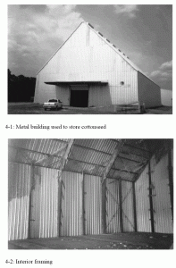
Two manufactured metal buildings were purchased and erected for use as agricultural product storage warehouses. The product stored was cottonseed. The cottonseed was separated from the seed in a gin building adjacent to each warehouse and then blown in for storage until it could be sold. The blower loaded the warehouses from one end, with the product removed through a door at the other end. The warehouses were intended to be fully loaded with cottonseed. Once the pile of cottonseed reached the peak of the roof, an auger built into the roof was used to move it toward the door. The warehouse storage capability would allow the owner to store cottonseed until it could be sold at a higher price. The two warehouses were located in towns about 32 km (20 mi) apart.
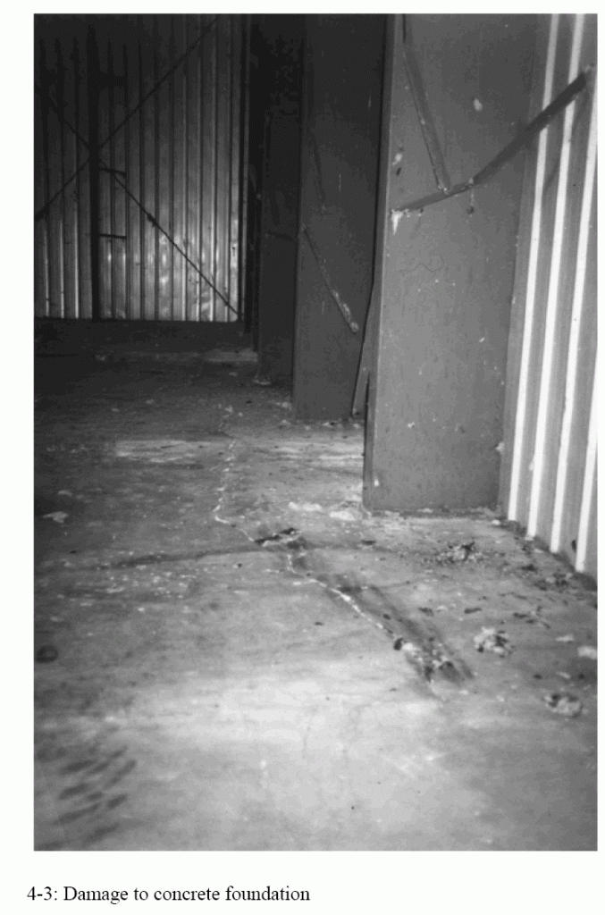
For two years, the warehouses were only partially loaded. During the third season, the warehouses were loaded to the roof, and workers outside of the building observed outward bulging of the warehouse walls. Once the product was removed, the concrete floor slabs were found to be badly cracked. The structure was also damaged, with evidence of permanent deformation. Much of the outward bulging disappeared when the cottonseed was removed, but the distortion in the metal walls remained.
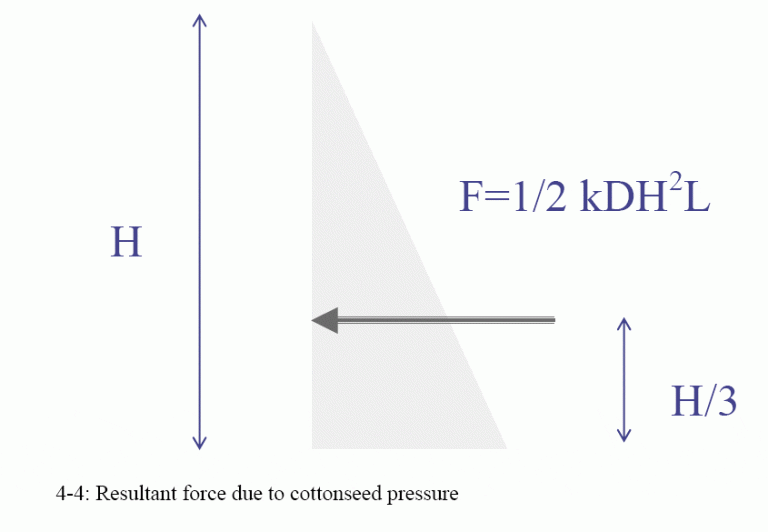
Stored agricultural products such as cottonseed or peanuts impose significant outward pressures on warehouse walls. These forces may be predicted using standard soil mechanics equations. Calculating these pressures is straightforward.
Because at least three of these warehouses have failed in the same predictable manner, it is clearly important for designers of future agricultural product warehouses to consider these forces in design. It is particularly important to consider overall structural stability under unbalanced product loads.
It is also necessary to make sure that the designer’s assumptions about structural behavior are consistent with the detailing. The column base connections were fixed but were modeled as if hinged. Either a fixed or a hinged connection could have been used, and the structure could have performed properly with either detail so long as the structure and foundation designs took the actual connection behavior into account. Instead, the moment that cracked the foundation slab was not accounted for by either the structural engineer or the foundation engineer.
The practice of splitting responsibility for a structure between a manufacturer’s structural engineer (who may know nothing about the site conditions) and a local foundation engineer (who may know nothing about metal building design and behavior) presents a high risk of failure. It is particularly dangerous when loading of this magnitude is present. A single engineer of record is needed to avoid poor performance that happens because of poor communication.
This case study is featured in Chapter 4 of the book Beyond Failure: Forensic Case Studies for Civil Engineers, Delatte, Norbert J., ASCE Press.
Original reference: Delatte, N. J. (2002). “Agricultural Product Loads and Warehouse Failures,” J. Perf. of Constr. Fac., 16(3), 116-123.
Illustrations from Chapter 4 of the book Beyond Failure: Forensic Case Studies for Civil Engineers, Delatte, Norbert J., ASCE Press.
Air Force Warehouses
Two warehouse roofs at Air Force Bases in Ohio and Georgia cracked and collapsed under combined load, shrinkage, and thermal effects in 1955 and 1956. 122 m (400 ft) lengths of reinforced concrete roof girders functioned as single units because of defective expansion joints. Other warehouses, built to the same plans, survived because the separation between adjacent two-hundred-foot bays was maintained by functioning joints. These failures led to more stringent shear reinforcing steel requirements in subsequent editions of the ACI Building Code. In the warehouse structures, the concrete alone, with no stirrups, was expected to carry the shear forces, and the members had no shear capacity once they cracked (McKaig 1962, Feld and Carper, 1997).
Wilkins Air Force Depot, 1955
At the Wilkins Air Force Depot in Shelby, Ohio, about 370 m2 (4,000 ft2) of the roof collapsed suddenly on August 17, 1955. At the time of the collapse, there were no loads other than the self-weight of the roof (Feld 1964, p. 25).
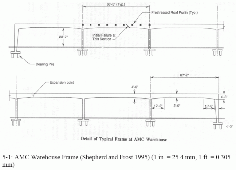
The Air Materiel Command (AMC) built warehouses to a common design at many Air Force bases and depots. The original design was developed in April 1952, with a modification to reinforcement made in March 1954. The Ohio warehouse had been built to the original 1952 design. It was a six-span rigid frame building, 122 m (400 ft) wide and 610 m (2,000 ft) long. The haunched rigid frames each had six 20 m (67 ft) spans and were spaced approximately 10 m (33 ft) on center. The concrete for each frame was placed continuously in a single working day. Vertical steel plate construction joints were set at the center of each span before concrete placement, but they may not have been effective (Feld 1964, p. 25).
Severe cracking had been observed two weeks before the collapse, so the girder had been supported by temporary shoring. The cracks occurred about 0.45 m (1 ft) past the end of the cutoff of the top negative reinforcement over the columns (Feld 1964, pp. 26- 27). A typical AMC warehouse frame is shown below.
Robins Air Force Base, 1956
A second warehouse roof collapse took place at Robins Air Force Base near Macon, Georgia, early on the morning of September 5, 1956. This warehouse had been built to the revised design. The revision added top bars and nominal stirrups, at a volume of about 0.06 %, for the length of the frames. This collapse included two adjacent girders and about 560 m2 (6,000 ft2) of the roof. Before the collapse occurred, cracks in the concrete girders that reached 13 mm in width had been observed. Feld (1964, p. 25) suggests It seems that the extent of shrinkage and resulting axial tensions may be somewhat related to the speed of concreting or to the extent of each separate placement.
In both cases, the design, materials, and workmanship were up to the codes and standards of the day. However, the failures had still occurred. Feld (1964, p 27) believed that failure took place by a combination of diagonal tension (shear) due to dead load and axial tension due to shrinkage and temperature change. Circumstantial evidence suggested that high friction forces were developed in the expansion joint consisting of one steel plate sliding on another; some plates showed no indication of relative displacement since their installation. In other words, the expansion joints locked and did not function to relieve stress.
Lessons Learned
Following these failures, construction of warehouse structures of this type was halted until a new design was developed. Existing warehouse frames were strengthened by adding external shear reinforcement consisting of tensioned steel strapping and steel angles at the lower corners of the girders. The ACI Building Code shear provisions were also revised (Feld 1964, pp. 27 -28).
Since these warehouse designs had been built in many locations, questions arose as to why these two warehouses had collapsed and not others. At the time of the collapse, these two structures were subject to wider temperature variations, and were about a year to a year and a half old. The temperature stresses, unrelieved by the locked expansion joints, combined with shrinkage and shear effects to cause high tensile stress. At the Wilkins Air Force Base ( Ohio ) structure, the failure plane did not cross any shear stirrups. The rapid, monolithic casting of the frames was thought to exacerbate shrinkage and to contribute to the problem (Feld and Carper 1997, pp. 255- 257).
Although it was not required by the code, many designers at that time used at least two continuous top bars and stirrups at a maximum spacing of 300 mm (12 in) along rectangular continuous beams. Following the two failures, tests were carried out at the Portland Cement Association (PCA) laboratories in Skokie,Illinois. Beams were tested with flexure only, and flexure plus axial tension. In the latter test, the beams under tension and flexure failed in the same manner as the two warehouse frames (Feld and Carper 1997, pp. 258 -259).
These two cases illustrate the importance of providing at least some minimum amount of reinforcement, called temperature steel, to resist tension forces due to thermal, shrinkage, and other effects. Real structures do not behave in the same way as our simplified models and develop forces and stresses where our analyses suggest there should be none. The shear resistance of unreinforced, cracked concrete is virtually nil. Feld (1964, p. 29) notes a similar warehouse slab collapse in which the crack through the slab did not cross any reinforcement, due to detailing error.
References:
McKaig, T. (1962). Building Failures: Case Studies in Construction and Design. McGraw-Hill, New York, N. Y.
Chapter 5 of Beyond Failure: Forensic Case Studies for Civil Engineers
Feld, J., and Carper, K. (1997). Construction Failure. 2nd Ed., John Wiley & Sons, New York, N. Y.
Bailey’s Crossroads, Virginia
Yet another formwork collapse blamed on inadequately cured concrete occurred at Bailey’s Crossroads, Virginia, in March 1973. Fourteen workers were killed and thirty were injured. Shores were removed between the 22nd and 23rd floors of the building while concrete was being placed on the 24th. The collapse tore a sixty-foot wide gap through the building all the way to the ground. The concrete, when tested, turned out to be well below its expected strength. The floor slab failed in punching shear at the columns (Ross 1984, Kaminetzky 1991, Feld and Carper 1997).
References:
- Feld, J., and Carper, K. (1997). Construction Failure. 2nd Ed., John Wiley & Sons, New York, N. Y
- Kaminetzky, D. (1991). Design and Construction Failures: Lessons from Forensic Investigations. McGraw-Hill, New York, N. Y.
- Ross, S. (1984), Construction Disasters: Design Failures, Causes, and Prevention. McGraw-Hill, New York, N. Y
Illustrations from Chapter 5 of the book Beyond Failure: Forensic Case Studies for Civil Engineers, Delatte, Norbert J., ASCE Press.
Bomber Crash into Empire State Building
On July 28, 1945, a ten-ton (10,000 kg) B-25 bomber crashed into the Empire State Building at an estimated 400 kph, into the north face of the 79th floor. Although several people were killed, the building remained standing (Levy and Salvadori, 1992).
To estimate the force applied to the building, we must estimate either the deceleration of the bomber as it crashed into the building (and use the force-acceleration method), estimate the distance it took the bomber to come to rest (and use work-energy), or estimate the time it took to bomber to come to rest (and use impulse-momentum). The bomber did not pass through the building, so a distance of 10 to 20 meters for the plane to come to rest could be used for calculations. If the bomber came to rest in 20 meters with a constant deceleration, the force would be about 4440 kilonewtons exerted over about 0.25 seconds.
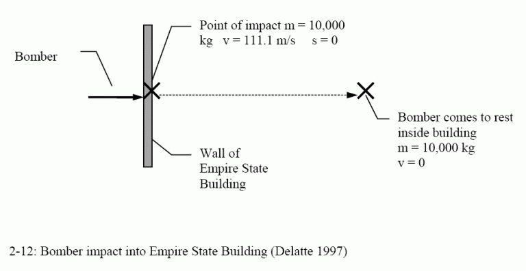
All three of these methods are derived from F = ma. The acceleration is assumed to be constant and is integrated once for velocity and twice for distance traveled. This problem is useful for demonstrating the equivalence of the three methods.
This case study was originally written in 1997 (Delatte, 1997), well before the terrorist attacks of September 11, 2001 (see World Trade Center and Pentagon). The same methods may be applied to calculate the impact forces applied by any aircraft of known weight and speed, with an estimate of the average distance before the aircraft (or its parts) came to rest.
Reference: Levy and Salvadori, 1992.
Citicorp Case Study
The case of William LeMessurier and the emergency repair of the Citicorp Center in New York City has been used by some as an example of ethical behavior by an engineer. This point of view is described in:
Morganstern, J., The Fifty-Nine-Story Crisis,ASCE Journal of Professional Issues in Engineering Education and Practice, Vol. 123, No. 1, Jan. 1997, also in the May 29, 1995, issue of The New Yorker
The abstract of the Morganstern paper states, “What’s an engineer’s worst nightmare? To realize that the wind-bracing system he designed for a skyscraper like Citicorp Center is flawed – a hurricane season is approaching. In 1978, William J. LeMessurier, one of the nation’s leading structural engineers, discovered after Citicorp Center was completed and occupied, conceptual errors pertaining to joint weakness, tension, and wind force. Alarmed by the magnitude of the errors and the danger they presented, LeMessurier acknowledged the flaws, immediately drew up new plans and saw that all of the necessary changes to the braces were put into effect. LeMessurier’s exemplary behavior – encompassing honesty, courage, adherence to ethics, and social responsibility – during the ordeal remains a testimony to the ideal meaning of the word, ‘professional.’ ”
The story is told much the same way at:
http://onlineethics.org/moral/LeMessurier/lem.html
Eugene Kremer takes a different view in his paper “(Re)examining the Citicorp Case: Ethical Paragon or Chimera” which may be found online at https://www.crosscurrents.org/kremer2002.htm
Kremer makes the following points, among others:
- The Citicorp Tower should have been checked for quartering winds because building codes require consideration of the most severe loading case.
- The decision to change welded joints to bolted joints was an important change that should have been considered more carefully.
- LeMessurier had a duty to publicize the problem with the building.
Some photos of the Citicorp Center, courtesy of Professor Bob Pitt at the University of Alabama
 |  |  |  |  |
Cleveland Lift-Slab Parking Garage
Although the final cause of the L Ambiance Plaza collapse has never been determined, the reason of the 1956 near-collapse of the Pigeonhole Parking Garage in Cleveland, Ohio appears obvious. This was also a lift-slab structure. The case is discussed in Chapter 4 of the book Beyond Failure: Forensic Case Studies for Civil Engineers, Delatte, Norbert J., ASCE Press.
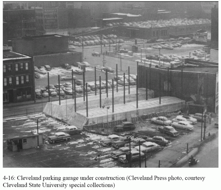
The building consisted of eight-story twin towers, 28 by 6.4 m each (91 by 21 ft) in the plan. The slabs were 200 mm (8 in) thick and weighed 800 kN (180,000 lb). The slabs had been jacked into place on 18.5 m (61 ft) tall columns spaced 6.7 m (22 ft) on center. All of the slabs of the west tower were in place, secured by temporary steel wedges. The structure before the incident is shown in figure 4-16.
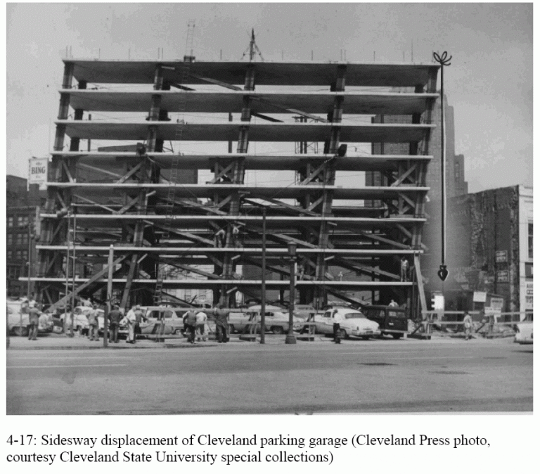
On the evening of April 6, winds gusted up to 56-80 kph (35 – 50 mph). The structure shifted 2.1 m (7 ft) out of plumb in the long direction, with the fifth floor very close to an adjacent building. The east tower, with only the second and third floors in place, was not affected by the wind. The sideways displacement of the Cleveland parking garage is shown in Figure 4-17.
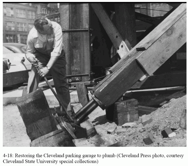
The building was secured with guys and temporary shoring on orders of the Cleveland building commissioner, who remarked if they had welded at each floor as they went along the building would have been braced and this would not have happened. The west tower was eventually jacked back into place (Feld 1964, pp. 93-94). The work to restore the Cleveland parking garage to plumb is shown in Figure 4-18.
The sequence of events is illustrated in photos published in the Cleveland Press newspaper, shown here as Figures 4-15 through 4-17. The newspaper is no longer published, but fortunately, its archives were passed on to the Cleveland State University Library special collections.
Also – see L-Ambiance Plaza Collapse
Illustrations from Chapter 4 of the book Beyond Failure: Forensic Case Studies for Civil Engineers, Delatte, Norbert J., ASCE Press.
Cold-Formed Steel Beam Construction Failure
During a concrete placement on the second story of a building under construction, the cold-formed steel beams supporting the decking and concrete collapsed. Four workers were injured, one fracturing his hip. Approximately two-thirds of the deck had been placed. The project structural engineer had been at the site earlier but had left before the collapse.
The collapse occurred while concrete was being placed onto steel decking on the second floor of the structure. The steel decking was supported by 203-mm (8-in.) deep cold-formed 1.21-mm (0.0478-in., 18 gauge) steel beams without shoring. Some of the workers raised concerns about the safety of the structure with the project structural engineer. He assured the contractor and workers that shoring was unnecessary and that the beams were rated for more than enough capacity to support the concrete.
The testimony of the workers and the photographs available indicated that good construction practices were followed with respect to placing and finishing the concrete. The project structural engineer contended that the failure occurred because workers allowed the concrete to form a pile on the formwork, thus increasing the loading.
Immediately before the collapse, concrete was being placed from a pump onto the decking. An experienced worker was using the pump nozzle to spread the concrete. The workers started at one end, moving toward the other end of the second floor. One worker claimed that the deck was vibrating during the concrete placement.
When approximately two-thirds of the concrete had been placed, the decking on the longer 4-m (13-ft) span gave way suddenly, and five of the workers fell. Two workers were able to grab wire mesh and avoid falling the entire distance. The others fell onto the first floor. One fell onto a plumbing fixture pipe and broke his pelvis. Photographs taken immediately after the collapse showed that the beams were bent at the interior wall support and at about the midpoint of the longer 4-m (13-ft) span. The damaged beams hung downward from the interior wall.
The structural integrity of the beams and decking was questioned, but the structural engineer provided assurances that they were adequate. No supporting documents were available.
The structural engineer contended that the collapse occurred because of poor construction practices, leading to concrete piling up and causing unbalanced loading. However, the testimony of the workers indicated that the concrete placement was carried out in accordance with good practice. There was no testimony from the workers or observers present that the workers allowed the concrete to pile up at any point on the decking. In fact, this would have made screeding and finishing the concrete much more difficult.
It is well known that the structural integrity of formwork for concrete is important. Hanna writes, “Partial or total failure of concrete formwork is a major contributor to deaths, injuries, and property damages within the construction industry” (Hanna 1999, p. 6).
The investigation was hampered because it was not possible to access the site and because the failed structure had been removed before the investigation started. Unfortunately, material samples had not been retained. Therefore, it was necessary to analyze the failure solely from the available documents and records.
There was only one engineer qualified by training, experience, and professional licensure on the project. The structural engineer should have consulted the proper references and performed the necessary structural calculations to ensure that the structure would be safe against collapse, under the load combinations prescribed by building codes. He should have analyzed the beam under an unbalanced load of concrete and live load and compared the calculated moments to the section capacities provided in the AISI manual (AISI 1996a).
There are important differences between design procedures for hot-rolled structural steel, which are taught in most civil engineering undergraduate programs, and those for cold-formed steel. Designing with cold-formed steel requires a knowledge of failure modes, such as local buckling, that can often be safely ignored with hot-rolled steel. Engineers designing with this material should take care to obtain the proper codes and design documents.
This case study is discussed in Chapter 6 of the book Beyond Failure: Forensic Case Studies for Civil Engineers, Delatte, Norbert J., ASCE Press.
References:
American Iron and Steel Institute. (AISI). (1996a). Cold-Formed Steel Design Manual, AISI, Washington, D.C. with errata.
American Iron and Steel Institute. (AISI). (1996b). Specification for the Design of Cold-Formed Steel Structural Members, Washington, D.C.
Delatte, N. J. (2005). “‘Failure of Cold-Formed Steel Beams during Concrete Placement,’ technical note.” J. Perf. of Constr. Fac., 19(2), 178-181.
Hanna, A. (1999). Concrete Formwork Systems, Marcel Dekker, Inc., New York.
Illustration from Chapter 6 of the book Beyond Failure: Forensic Case Studies for Civil Engineers, Delatte, Norbert J., ASCE Press.
Harbor Cay Condominium, Cocoa Beach, Florida
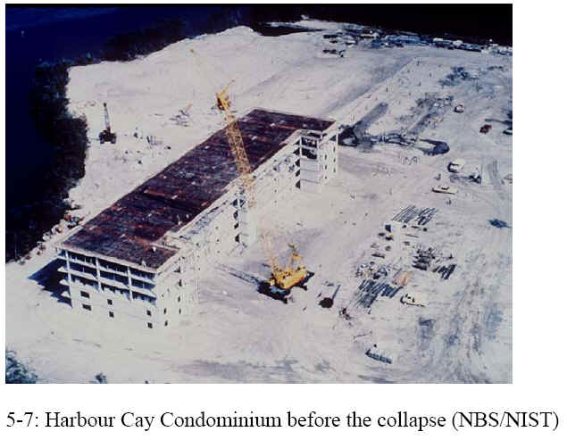
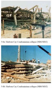
Numerous design errors were uncovered when the five-story Harbor Cay Condominium, Cocoa Beach, Florida, collapsed under construction in 1981, killing eleven workers and injuring twenty-three. Incredibly, no punching shear calculation had been made for the concrete floor slabs. Furthermore, the slabs were only 200 mm (eight inches) thick and should have been 280 mm (eleven inches) thick to satisfy the ACI Building Code minimum. The chairs used to support the slab steel were 108 mm (4 inches) high, which coupled with the thin slabs led to a very small effective depth (McKaig 1962, Kamintzky 1991).
References:
- Chapter 5 of the book Beyond Failure: Forensic Case Studies for Civil Engineers, Delatte, Norbert J., ASCE Press.
- Kaminetzky, D. (1991). Design and Construction Failures: Lessons from Forensic Investigations. McGraw-Hill, New York, N. Y.
- Lew, H. S. et al. (1982). Investigation of construction failure of Harbour Cay Condominium in Cocoa Beach, Florida. Rep., U.S. Dept. of Comm., Nat. Bureau of Standards, S/N 003-003-0245-8, Washington, D. C.
- McKaig, T. (1962). Building Failures: Case Studies in Construction and Design. McGraw-Hill, New York, N. Y.
Illustrations from Chapter 5 of the book Beyond Failure: Forensic Case Studies for Civil Engineers, Delatte, Norbert J., ASCE Press.
Hartford Civic Center
Higher than expected deformations may indicate that the structure is overloaded. At approximately 4:15 a.m. on January 17, 1978, the roof of the Hartford Civic Center Arena collapsed. Only six hours earlier, five thousand people had been in the arena watching a basketball game. The arena roof was a 90 by 110-meter space frame (Levy and Salvadori, 1992, Kaminetzky, 1991, Feld and Carper,1997).
During construction in 1972 and 1973, the inspection agency notified the engineers of excessive deflections (Levy and Salvadori, 1992). The measured deflection of the roof was twice that predicted by computer analysis. On the day of the collapse, the sum of dead and live loads was less than the design load.
The large deformations were a warning that the structure was not behaving as the computer model had predicted, and was on the verge of collapse (Levy and Salvadori, 1992). Kaminetzky (1991) suggests that the deformations were cries for help from the structure.
This case study can be introduced early in a mechanics of materials course when member deformations are first taught, and then discussed again when elastic buckling is encountered. Numerous factors contributed to the collapse, among them that the main top chords had a much lower buckling capacity than assumed in the original design analysis. The unbraced length of some compression members was 9.14 meters rather than the assumed 4.57 meters; thus, the capacity was reduced 75 % by this factor alone. Other factors reduced member capacity even further (Feld and Carper, 1997), and this case study could be revisited several times to bring out specific points about three-dimensional structural behavior, and the dangers of over-reliance on two-dimensional models.
What measures should be taken when observed structural deformations greatly exceed predicted deformations? Should a structure that will kill five thousand people if it collapses be designed with greater care and a higher factor of safety (Kaminetzky, 1991)
Rachel Martin’s Case Study – originally developed for the UAB REU Site, 1999
Hartford Civic Center Arena Roof Collapse
Hartford, Connecticut
January 18, 1978
By Rachel Martin
| Design and ConstructionCollapseCauses of FailureLegal RepercussionsTechnical ConcernsProcedural ConcernsEthical ConcernsBibliography | 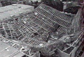 Hartford CT, Civic Center Coliseum roof collapse, 1978 (Feld and Carper, 1997) Hartford CT, Civic Center Coliseum roof collapse, 1978 (Feld and Carper, 1997) |
Design and Construction
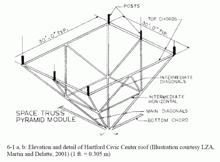
In 1970 Vincent Kling agreed to be the architect for the Hartford civic center. Shortly thereafter he hired Fraoli, Blum, and Yesselman, Engineers (F, B,&Y) to design the arena. In order to save money, F, B,&Y proposed an innovative design for the 300 by 360 ft. space frame roof over the arena. The proposed roof consisted of two main layers arranged in 30 by 30-ft grids composed of horizontal steel bars 21-ft apart. 30-ft diagonal bars connected the nodes of the upper and lower layers, and, in turn, were braced by a middle layer of horizontal bars. The 30-ft bars in the top layer were also braced at their midpoint by intermediate diagonal bars.

Space Frame Roof

Section of the Space Frame Roof
This design departed from standard space frame roof designing procedures in five ways.
- The configuration of the four steel angles did not provide good resistance to buckling. The cross-shaped built up section has a much smaller radius of gyration than either an I-section or a tube section.
 |  |  |
- The top horizontal bars intersected at a different point than the diagonal bars rather than at the same point, making the roof especially susceptible to buckling.
- The top layer of this roof did not support the roofing panels; the short posts on the nodes of the top layer did. Not only were these posts meant to eliminate bending stresses on the top layer bars, but their varied heights also allowed for positive drainage.
- Four pylon legs positioned 45-ft inside of the edges of the roof supported it instead of boundary columns or walls (Levy and Salvadori, 1992).
- The space frame was not cambered. Computer analysis predicted a downward deflection of 13-in at the midpoint of the roof and an upward deflection on 6-in at the corners. These deflections were taken into account (ENR, Jan 26, 1978).
Because of these money-saving innovations, the engineers employed state of the art computer analysis to verify the safety of the building.
A year later construction began. To save time and money, the roof frame was completely assembled on the ground. While it was still on the ground the inspection agency notified the engineers that it had found excessive deflections in some of the nodes. Nothing was done. After the frame was completed, hydraulic jacks located on top of the four pylons slowly lifted it into position. Once the frame was in its final position but before the roof deck was installed, its deflection was measured to be twice that predicted by computer analysis, and the engineers were notified. They, however, expressed no concern and responded that such discrepancies between the actual and the theoretical should be expected (Levy and Salvadori,1992). When the subcontractor began fitting the steel frame supports for fascia panels on the outside of the truss he ran into great difficulties due to the excessive deflections of the frame. Upon notification of this problem, the general contractor “directed the subcontractor to deal with the problem or be responsible for delays.” As a result, the subcontractor coped some of the supports and prefabricated others in order to make the panels fit, and construction continued (ENR, April 6, 1978). The roof was completed on January 16, 1973 (Feld and Carper, 1997). The next year, a citizen expressed concern to the engineers concerning the large downward deflection he noticed in the arena roof, which he believed to be unsafe. The engineers and the contractor once again assured the city that everything was fine (Levy and Salvadori, 1992).
Collapse
On January 18, 1978, the Hartford Arena experienced the largest snowstorm of its five-year life. At 4:15 A.M. with a loud crack the center of the arena’s roof plummeted the 83-feet to the floor of the arena throwing the corners into the air. Just hours earlier the arena had been packed for a hockey game. Luckily it was empty by the time of the collapse, and no one was hurt.
Causes of Failure
Hartford appointed a three-member panel to manage the investigation of the collapse. This panel, in turn, hired Lev Zetlin Associates, Inc. (LZA) to ascertain the cause of the collapse and to propose a demolition procedure. LZA discovered that the roof began failing as soon as it was completed due to design deficiencies. A photograph taken during construction showed obvious bowing in two of the members in the top layer. Three major design errors coupled with the underestimation of the dead load by 20% (estimated frame weight = 18 psf, actual frame weight = 23 psf) allowed the weight of the accumulated snow to collapse the roof. The load on the day of the collapse was 66-73 psf, while the arena should have had a design capacity of at least 140 psf. The three design errors responsible for the collapse are listed below.
- The top layer’s exterior compression members on the east and the west faces were overloaded by 852%
- The top layer’s exterior compression members on the north and the south faces were overloaded by 213%.
- The top layer’s interior compression members in the east-west direction were overloaded by 72%.
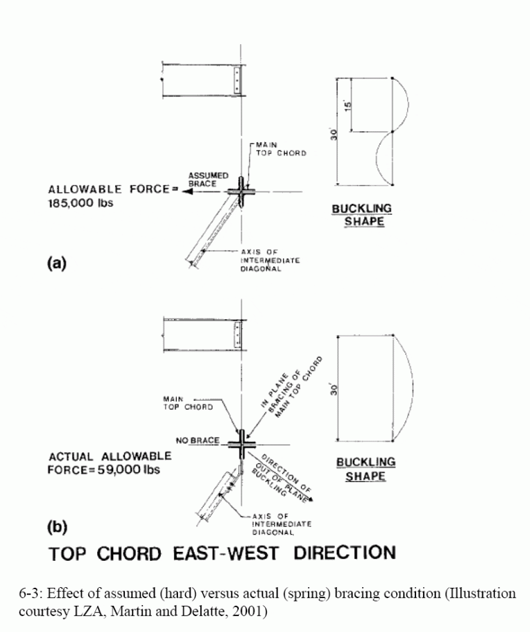
In addition to these errors in the original design, LZA discovered that the details omitted the midpoint braces for the rods in the top layer. The exterior rods were only braced every 30-feet, rather than the 15-feet intervals specified, and the interior rods were only partially and insufficiently braced at their midpoints. This significantly reduced the load that the roof could safely carry. The table below compares some of the original details to actual designs used in the building, demonstrating the reduction in strength that these changes caused. Connection A was typically used on the east-west edges of the roof, while connection B was used on the north-south edges. Most of the interior bars used connection C, while a few used connection D. The key difference between the original and the as-built details is that the diagonal members were attached some distance below the horizontal members, and thus were unable to brace the horizontal members against buckling.
| Connection A | Connection B | Connection C | Connection D | |
| OriginalDesign |  Allowable force: 160,000-lb Allowable force: 160,000-lbAllowable moment: 0 |  Allowable force: 185,000-lb Allowable force: 185,000-lb |  Allowable force: 625,000-lb Allowable force: 625,000-lb |  Allowable force: 565,000-lb Allowable force: 565,000-lb |
| As-builtDesign |  Allowable force: 15,440-lb Allowable force: 15,440-lb Allowable moment: 9,490 lb-ft |  Allowable force: 59,000-lb Allowable force: 59,000-lb |  Allowable force: 363,000- lb Allowable force: 363,000- lb |  Allowable force: 565,000-lb Allowable force: 565,000-lb |
Original vs. Actual Design
*Drawings by Rachel Martin
he most overstressed members in the top layer buckled under the added weight of the snow, causing the other members to buckle. This changed the forces acting on the lower layer from tension to compression causing them to buckle also. Two major folds formed initiating the collapse. These were not the only errors that LZA discovered. Listed below are other factors which contributed to, but could not have caused, the collapse.
- The slenderness ratio of the built-up members violated the American Institute of Steel Construction (AISC) code provisions.
- The members with bolt holes exceeding 85% of the total area violated the AISC code (ENR, June 22, 1978).
- The spacer plates were placed too far apart in some of the four-angle members allowing individual angles to buckle.
- Some of the steel did not meet specifications.
- There were misplaced diagonal members (Feld and Carper, 1997).
Loomis and Loomis, Inc. also investigated the Hartford collapse. They agreed with LZA that gross design errors were responsible for the progressive collapse of the roof, beginning the day that it was completed. They, however, believed that the torsional buckling of the compression members, rather than the lateral buckling of top chords, instigated the collapse. Using computer analysis, Loomis and Loomis found that the top truss rods and the compression diagonals near the four support pylons were approaching their torsional buckling capacity the day before the collapse. An estimated 12 to 15 psf of live load would cause the roof to fail. The snow from the night before the collapse comprised a live load of 14 to 19 psf. Because torsional buckling is so uncommon, it is often an overlooked mode of failure.
Hannskarl Bandel, a structural consultant, completed an independent investigation of the collapse of architect’s insurance company. He blamed the collapse on a faulty weld connecting the scoreboard to the roof. This opinion conflicts with the opinions of all the other investigators.
Legal Repercussions
Six years after the collapse, all of the parties reached an out-of-court settlement. While this was beneficial to the parties involved, it robbed the engineering world of the precedents that such a case could set. The issue of who ultimately holds responsibility for the structural integrity of a project when the tasks are divided among numerous subcontractors or if anyone does was never resolved.
Technical Concerns
The engineers for the Hartford Arena depended on computer analysis to assess the safety of their design. Computers, however, are only as good as their programmer and tend to offer engineers a false sense of security. The roof design was extremely susceptible to buckling which was a mode of failure not considered by in that particular computer analysis and, therefore, left undiscovered. A more conventional roof design would have been much stronger. Instead of the cruciform shape of the rods, a tube or I-bar configuration would have been much more stable and less vulnerable to bending and twisting. Also, if the horizontal and diagonal members intersected at the same place it would have reduced the bending stresses in these members. Finally, the failure of a few members would not have triggered such a catastrophic collapse if the structure had been designed and built with more redundancy.
Procedural Concerns
The Hartford Arena contract was divided into five subcontracts coordinated by a construction manager. Not only did this fragmentation allow mistakes to slip through the cracks, but it also left confusion over who was responsible for the project as a whole. Even though the architect recommended that a qualified structural engineer be hired to oversee the construction, the construction manager refused saying that it was a waste of money and that he would inspect the project himself. After the collapse he disclaimed all responsibility on the grounds that a design error had caused the collapse. He believed that he was only responsible for ensuring that the design was constructed correctly and not the performance of the project. It is important for the responsibility for the integrity of the entire project to rest with one person. Fragmented responsibility leaves no one with a sense of or a real concern for how everything will work together making errors more likely to go undetected.
As a result of the construction manager’s refusal to hire a structural engineer for the purpose of inspection, no one realized the structural implications of the bowing structures. This collapse illustrates the importance of having a structural engineer, especially the designer, perform the field inspection. The designer understands the structure that is being built and would best be able to recognize the warning signs of bad design and rectify them before they grow to catastrophic proportions.
Finally, the Hartford department of licenses and inspection did not require the project peer review of the arena design, which it usually did for projects of this magnitude. If a second opinion had been required the design deficiencies responsible for the arena’s collapse probably would have been discovered. Peer reviews are an essential safety measure for all high capacity buildings and structures experimenting with new design techniques.
Ethical Concerns
The excessive deflections apparent during construction were brought to the engineer’s attention multiple times. The engineer, confident in his design and the computer analysis which confirmed it, ignored these warnings and did not take the time to recheck its work. An ethical engineer would pay close attention to unexpected deformations and investigate their causes. They often indicate structural deficiencies and should be investigated and corrected immediately. Unexpected deformations provide a clear signal that the structural behavior is different from that anticipated by the designer. Also, this collapse raises the important question of whether the factor of safety should be increased for buildings with high occupancy. Should the impact of a possible failure be taken into account in determining the factor of safety?
Bibliography
“Collapsed Roof Design Defended.” ENR, June 29,1978.
“Collapsed Space Truss Roof Had a Combination of Flaws.” ENR, June 22, 1978.
“Design Flaws Collapsed Steel Space Frame Roof.” ENR, April 6, 1978.
The Education Committee of the Technical Council on Forensic Engineering of the American Society of Civil Engineers [ASCE]. Shepherd, Robin and David Frost (Eds.). (1995). Failures in Civil Engineering: Structural, Foundation, and Geoenvironmental Case Studies. New York: The Society.
Feld, Jacob, and Carper, Kenneth, Construction Failure (1997), 2nd Ed., John Wiley & Sons, New York, N.Y.
“Hartford Collapse Blamed on Weld.” ENR, June 24, 1979.
Kaminetzky, Dov, Design and Construction Failures: Lessons from Forensic Investigations (1991). McGraw-Hill, New York, N.Y.
Levy, Matthys and Salvadori, Mario (1992), Why Buildings Fall Down: How Structures Fail. W. W. Norton, New York, NY.
“New Theory on Why Hartford Roof Fell.” ENR, June 14, 1979.
Petroski, Henry (1985), “From Slide Rule to Computer,” To Engineer Is Human. St. Martins Press, New York, NY.
Ross, S. et al. (1984), “Hartford Civic Center, 1978.” Construction Disasters. McGraw-Hill Book Co, New York, NY.
“Space Frame Roofs Collapse Following Heavy Snowfalls.” ENR, January 26, 1978.
Illustrations from Chapter 6 of the book Beyond Failure: Forensic Case Studies for Civil Engineers, Delatte, Norbert J., ASCE Press.
Kemper Arena
The Kemper Arena opened in 1973 as the new home of the Kansas City Kings basketball team. Because the roof was suspended from above, it featured uninterrupted sight lines. The innovative design earned the architect an Honor Award from the American Institute of Architects (AIA), and the AIA held its 1979 annual convention in Kansas City. Word of the collapse came to the AIA meetings opening banquet (Wearne 2000, pp. 26 -27).
The Kemper Arenas large flat roof, 97 by 108 m (324 by 360 ft.) was suspended on hangers from 3 large space frame cantilever trusses. The three trusses, each 16.5 m (54 ft) wide, were spaced 30 m (99 ft) apart and were made from pipe sections as large as 1.2 m (4 ft) in diameter (Levy and Salvadori, 1992, pp. 57 -67).
Each of the 42 hangers supporting the roof carried 622 kN (140 kips) in tension. The hangers used ASTM A490 high strength bolts, which are not recommended for variable or fatigue loads.
In order to reduce the stormwater runoff into the city storm sewers, the roof was designed to hold water as a temporary reservoir. The roof only had eight 130 mm (5 in) diameter drains. The local code actually required eight times as many. Once the water depth exceeded 50 mm (2 in) water could pour out over scuppers. This feature could obviously aggravate ponding.
At 6:45 pm a storm was dumping 108 mm (4 in) of rain per hour, along with wind gusting to 112 kph (70 mph). One arena employee present heard strange noises, followed by explosive bangs. He barely had time to flee. A portion of the roof approximately 60 by 65 m (200 by 215 ft) collapsed into the arena. The pressure wave from the falling roof segment blew out some of the arena walls (Levy and Salvadori, 1992, pp. 57-67).
A report prepared by Weidlinger Associates, working on behalf of a subcontractor, found
- The hangers had probably been weakened by fatigue cycles over the five years the arena had been open
- The roof was susceptible to ponding, and the wind pushed the water to pile up near the point of failure.
- It was necessary to analyze the roof in three dimensions, not just two, to determine the actual flexibility and ponding susceptibility of the roof
- One hanger fractured from the combined action of wind and water ponding weight
- Once one hanger failed, the roof had no redundancy. The other hangers could not carry the additional load, and several more failed.
The Kemper Arena collapse is discussed by Levy and Salvadori (1992, pp. 57-67) and also by Wearne (2000, pp. 25- 36). This case study is featured on the History Channel Modern Marvels More Engineering Disasters videotape/DVD.
This case study is discussed in Chapter 4 of the book Beyond Failure: Forensic Case Studies for Civil Engineers, Delatte, Norbert J., ASCE Press.
L’Ambiance Plaza Collapse
It is important that the designer provides a continuous load path at all times to transfer all loads safely to the foundation. There are many competing theories as to why the L’Ambiance Plaza Towers collapsed while under construction, but each theory is based on a break in the load path. The state of construction just before collapse is illustrated below, which shows an elevation of the building with the packages of slabs being jacked up together. Five theories are discussed on Rachel Martin’s web page. Several of the theories focus on the lift heads that were used to lift the slabs in position.
Rachel Martin’s Case Study – originally developed for the UAB REU Site, 1999
L’Ambiance Plaza Collapse
Bridgeport, Connecticut
April 23, 1987
By Rachel Martin
| Design and ConstructionCollapseCauses of FailureLegal RepercussionsTechnical ConcernsProcedural ConcernsEthical ConcernsLinksBibliography | 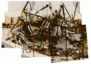 Ruins of L’Ambiance Plaza Ruins of L’Ambiance Plaza |
Design and Construction
L’Ambiance Plaza was planned to be a sixteen-story building with thirteen apartment levels topping three parking levels. It consisted of two offset rectangular towers, 63 ft by 112 ft each, connected by an elevator. Seven-inch thick post tensioned, concrete slabs and steel columns comprised its structural frame. Posttensioning overcomes the tensile weakness of concrete slabs by placing high strength steel wires along their length or width before the concrete is poured. After the concrete hardens, hydraulic jacks pull and anchor the wires compressing the concrete.
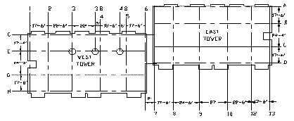
Floor Plan of L’Ambiance Plaza
The lift-slab method of construction, patented by Youtz and Slick in 1948, was utilized in the construction of this building. Following this technique, the floor slabs for all sixteen levels were constructed on the ground, one on top of the other, with bond breakers between them. Then packages of two or three slabs were lifted into temporary position by a hydraulic lifting apparatus and held into place by steel wedges. This hydraulic lifting apparatus consisted of a hydraulic jack on top of each column with a pair of lifting rods extending down to lifting collars cast in the slab. Once the slabs were positioned correctly, they were permanently attached to the steel columns. Two shear walls in each tower were to provide the lateral resistance for the completed building on all but the top two floors. These two floors depended on the rigid joints between the steel columns and the concrete slabs for their stability. Since the shear wall played such an indispensable role in the lateral stability of the building, the structural drawings specified that during construction the shear walls should be within three floors of the lifted slabs.
Collapse
At the time of collapse, the building was a little more than halfway completed. In the west tower, the ninth, tenth, and eleventh floor slab package was parked in stage IV directly under the twelfth floor and roof package. The shear walls were about five levels below the lifted slabs. The workmen were tack welding wedges under the ninth, tenth, and eleventh floor package to temporarily hold them into position when they heard a loud metallic sound followed by rumbling. Kenneth Shepard, an ironworker who was installing wedges at the time, looked up to see the slab over him “cracking like ice breaking.” Suddenly, the slab fell on to the slab below it, which was unable to support this added weight and in turn fell. The entire structure collapsed, first the west tower and then the east tower, in 5 seconds, only 2.5 seconds longer than it would have taken an object to free fall from that height. Two days of frantic rescue operations revealed that 28 construction workers died in the collapse, making it the worst lift-slab construction accident. Kenneth Shepard was the only one on his crew to survive.
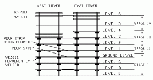
Status of Construction at Time of Collapse
*Figure by Rachel Martin
Causes of Failure
An unusually prompt legal settlement prematurely ended all investigations of the collapse. Consequently, the exact cause of the collapse has never been established. The building had a number of deficiencies; any one of which could have triggered the collapse. The question, however, remains which one of these failed first, triggering the rest of the failures and ultimately total collapse. There are five competing theories as to the trigger.
Theory 1: National Bureau of Standards (NBS) – An overloaded steel angle welded to a shearhead arm channel deformed, causing the jack rod and lifting nut to slip out and the collapse to begin.
Theory 2: Thornton-Tomasetti Engineers (T-T) – The instability of the wedges holding the twelfth floor and roof package caused the collapse.
Theory 3: Schupack Suarez Engineers, Inc. (SSE) – The improper design of the post tensioning tendons caused the collapse.
Theory 4: Occupational Safety and Health Administration (OSHA) – Questionable weld details and substandard welds could have caused the collapse.
Theory 5: Failure Analysis Associates, Inc. (FaAA) The sensitivity of L’Ambiance Plaza to lateral displacement caused its collapse.
Theory 1
The NBS investigation concluded that the failure occurred at the buildings most heavily loaded column E4.8 or the adjacent column E3.8 as a result of a lifting assembly failure. The shearhead reinforces the concrete slab at each column, transfers vertical loads from the slabs to the columns, and provides a place of attachment for the lifting assembly. It consists of ]-shaped steel channels cast in the concrete slab leaving a space for the lifting angle. The lifting angle has holes to pass the lifting rods through. These rods are raised by the hydraulic jacks on the columns above them.
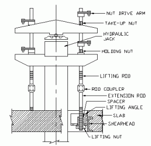
Lifting Assembly
Shortly before the collapse the workers lifted the 9th, 10th, and 11th-floor package to its final position and began tack-welding the steel wedges into place. They used a jack on top of the column E4.8 or E3.8 to slightly adjust the position of the slab overloading the lifting angles. When the shearheads and lifting angles had lifted the package of three 320-ton slabs, they were dangerously close to their maximum capacity, so adding even the smallest of loads could strain them. One of the reasons was that the lifting capacities of the two types of jacks used were too small for the 960-ton package being lifted. The regular jacks have a maximum load of 89 tons, while the super jacks have a maximum load of 150 tons. NBS also tested the shearhead and lifting angle and found that they tended to twist as the loads approached 80 tons because although strong enough, they were not rigid enough. The excess force deformed the lifting angle allowing the jack rod and lifting nut to slip out of the lifting angle and hit the column with 75,000 lb of force. This accounts for the loud noise that Kenneth Shepard heard and the indention found in that column. After this initial slip, the jack rods and lifting nuts in the entire E line progressively slipped causing the ninth floor slab to collapse, initiating the collapse of the entire building.
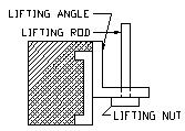 | 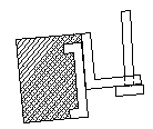 | 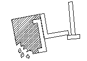 |
Failure Sequence Theory 2
Theory 2
Thornton-Tomasetti Engineers (T-T) concluded at the end of their investigation that the instability of the wedges at column 3E caused the 12th floor/ roof package to fall initiating the collapse. Unlike the NBS investigation, their investigation found that all the wedges supporting the 9th/10th/11th-floor package were mounted prior to the collapse and that that column had no indentations on it. They, however, did find abnormal tack welds on the wedges which supported the 12th floor/roof package, a large deformation on the top edge of the west wedge of this set, and indentations on the underside of the level 9 shearhead. The shallowness of the indentations indicated that, while both lifting nuts slipped out, they were not heavily loaded at the time. Their investigation also found that the shearhead gaps on columns 3E and 3.8E (0.628 in) were much larger than the gaps on the rest of the building (0.233 in- 0.327 in) and other buildings built with the lift-slab technique (0.250 in – 0.375 in). In addition to these abnormally large gaps, the shearheads used on these two columns did not have cut outs in their lifting angles to restrict relative shifting and were installed eccentrically. Finally, until a wedge is completely welded into place it depends on friction to hold it. Normally, this is sufficient. The large shearhead gaps on columns 3E and 3.8E and the presence of hydraulic fuel on these wedges, however, would have demanded an extremely high friction coefficient to hold the wedges into place.
On the day of the collapse, the lateral load from the hydraulic jack exerted on the heavily loaded wedges caused the west wedge to roll. Then the local adjustments to slab elevations caused the remaining wedge to roll out initiating the collapse of the 11th floor/roof package and the west tower. Forces transmitted through the pour strips or the horizontal jack or the impact of the debris from the west tower triggered the east towers collapse.
Theory 3
SSE analyzed the structural behavior of a typical west tower floor slab under ideal conditions with regards to the unusual layout of the posttensioning tendons.
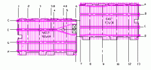
General layout of post-tensioning tendons
*each line represents 1-5 monostrand tendons which are shown in magenta
The tendons in the east tower follow a typical two-way banded post tensioning tendon layout. In this layout, the vertical tendons distribute the weight of the slab to the east-west column lines which in turn distribute the weight to the columns. The west tower, however, deviates from this pattern. At column 4.8E the tendons split in two, both diverging from the column line. In the west tower, the vertical tendons still distribute the slab’s weight to the column line. In line E, however, there are no tendons to carry this weight. This setup violates the American Concrete Institute (ACI) building-code. Also, the design details of the post-tensioned floor slabs do not show the location of the shear walls or the openings for the walls at columns 11A, 8A, and 2H. The design did not take these opening into account. Detailed finite element analysis showed that tensile stresses along column line E, east of column 4.8E, exceeded the cracking strength of the concrete. Therefore once a crack began, it would immediately spread to column 4.8E. In addition under ideal lifting conditions, column 2H demonstrated unsuitably high compressive and punching shear stresses (Poston, Feldmann, and Suarez, 1991).
Theory 4
OSHA found that the header bar-to-channel welds on one side of the 9th-floor shearhead at column E3.8 had failed. The use of one-sided square-groove welds for the header bar-to-channel connection was dubious from the start since they were not prequalified joints according to the American Welding Society. Because their penetration was not known, their strength could not be determined. OSHA hired Neal S Moreton and Associates to examine 30 welds around the shearheads at column E3.8 at the 7th, 8th, and 10th floors. They found only 13 of the 30 welds acceptable; the other 17 were substandard. The questionable weld details and the substandard welding coupled with drawings that indicated that the welds would undoubtedly experience forces that they could not resist all point to weld failure as the trigger of the collapse.
Theory 5
The FaAA studied the towers torsional instability and reaction to lateral loading to understand its collapse. When the concrete slabs are temporarily resting on the wedges, the connection is rotationally stiff, but as soon as the slab is lifted off one of the wedges into its final position it can rotate freely from the column. Once the wedges are fully welded into their final position the connection becomes rigid again. In the absence of lateral loading, the tower is completely stable.
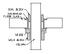
Wedged Slab-to-Column Connection
Lateral loading and displacement, however, can cause the slab to lift off one of its wedges causing the structure to become laterally flexible. The FaAA used 3-D computer modeling (ANSYS) and nonlinear stability modeling to study this phenomenon. Their investigation and analysis lead them to the conclusion that the towers sensitivity to lateral displacement caused its collapse. While the FaAA acknowledges that another mechanism could have triggered the lateral displacement, they believe that lateral jacking provided sufficient displacement to initiate the collapse.
Legal Repercussions
A two-judge panel mediated a universal settlement between 100 parties closing the L’Ambiance Plaza case. Twenty or more separate parties were found guilty of “widespread negligence, carelessness, sloppy practices, and complacency.” They all contributed, in varying amounts, to the $41 million settlement fund. Those injured and the families of those killed in the collapse received $30 million. Another $7.6 million was set aside to pay for all of the claims and counter-claims between the designers and contractors of L’Ambiance Plaza. While this settlement kept hundreds of cases out of court and provided rapid closure to a colossal collapse, it also ended all investigations prematurely, leaving the cause of collapse undetermined.
Technical Concerns
While buildings constructed by the lift-slab method are stable once they are completed if great care is not taken during construction they can be dangerous. The following measures can be taken to ensure lateral stability and safety during construction.
- During all stages of construction, temporary lateral bracing should be provided.
- Concrete punching shear and connections redundancies should be provided in the structure (Kaminetzky, 1991).
- Cribbing (temporary posts which support the concrete slab until it is completely attached to the column) should be used.
- Sway bracing (cables which keep the stack of floors from shifting sideways) should be used. This was required, but not used in L’Ambiance Plaza (Levy and Salvadori, 1992).
Due to the terms of the settlement, many of the technical lessons that could have been learned from this incident have been lost forever.
Procedural Concerns
The L’Ambiance Plaza collapse highlighted several procedural deficiencies. Responsibility for design was fragmented among so many subcontractors that several design deficiencies went undetected. If the engineer of record had taken responsibility for the overall design of the building or a second engineer had reviewed the design plans these defects probably would have been detected. Also, standardized step-by-step procedures for lift-slab construction should be established to ensure the safety of the construction workers. A licensed professional engineer should be present during construction to ensure that these guidelines are followed.
Ethical Concerns
While L’Ambiance Plaza was designed to be safe once it was completed, during construction it had a considerably lower factor of safety. This is all too common in the construction industry today. Canon 1 of the American Society of Civil Engineers (ASCE) Code of Ethics states, “Engineers shall hold paramount the safety, health and welfare of the public and shall strive to comply with the principles of sustainable development in the performance of their professional duties”. This includes the safety of construction workers. Building regulations do not sufficiently consider structural safety during construction and should be changed to require a high standard of safety during construction as well as after a buildings completion. In the absence of such regulations, however, an ethical engineer must always consider the safety of the workers.
Links
Public Safety Issues in the Collapse of L’Ambiance Plaza
L’Ambiance Plaza Gift to Fund Health and Safety Training
Bibliography
ASCE Code of Ethics. [Online] Available https://www.asce.org/aboutasce/codeofethics.html, Sept 28, 1998.
Cuoco, Daniel (1992), “Investigation of L’Ambiance Plaza Building Collapse.” Journal of Performance of Constructed Facilities, November 1992.
Feld, Jacob, and Carper, Kenneth, Construction Failure (1997), 2nd Ed., John Wiley & Sons, New York, N.Y.
Heger, Frank (1991), “Public-Safety Issues in Collapse of L’Ambiance Plaza.” Journal of Performance of Constructed Facilities, May 1991.
Kaminetzky, Dov, Design and Construction Failures: Lessons from Forensic Investigations (1991). McGraw-Hill, New York, N.Y.
Korman, Richard (May 5, 1988), “Architect’s Dual Role Criticized.” ENR, May 5, 1988
Korman, Richard (1987), “Flawed Connection Detail Triggered Fatal L’Ambiance Plaza Collapse.” ENR, October 29, 1987.
Korman, Richard (Nov 24, 1988), “Mediated Settlement Seeks to Close the Book on L’Ambiance Plaza.” ENR, November 24, 1988.
Korman, Richard (1991), “New Twist in Lift-Slab Case.” ENR, July 1/8, 1991.
Levy, Matthys and Salvadori, Mario (1992), Why Buildings Fall Down: How Structures Fail. W. W. Norton, New York, NY.
McGuire, William (1992), “Comments on L’Ambiance Plaza Lifting Collar/Shearheads.” Journal of Performance of Constructed Facilities, May 1992.
Moncarz, Piotr, Hooley, Roy, Osteraas, and John, Lahnert (1993), “Analysis of Stability of L’Ambiance Plaza Lift-Slab Towers.” Journal of Performance of Constructed Facilities, April 1, 1993.
Poston, Randall, Feldmann Gerard, and Suarez, Mario (1991), “Evaluation of L’Ambiance Plaza Posttensioned Floor Slabs.” Journal of Performance of Constructed Facilities, May, 1991.
Ruins of L’Ambiance Plaza. [Online Image] Available https://www.sgh.com/aplaza.htm, July 25, 1999.
Veillieux, Richard (1998), “Last of L’Ambiance Plaza Settlement Goes to Labor Center.” University of Connecticut, Feb 17, 1998.
Illustrations from Chapter 4 of the book Beyond Failure: Forensic Case Studies for Civil Engineers, Delatte, Norbert J., ASCE Press.
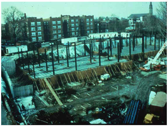
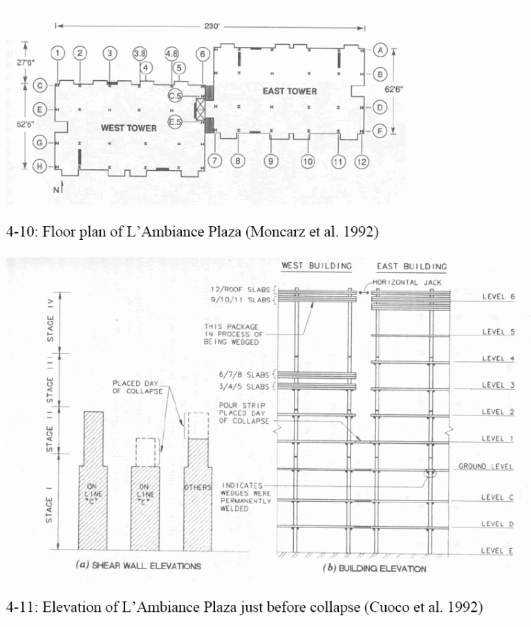
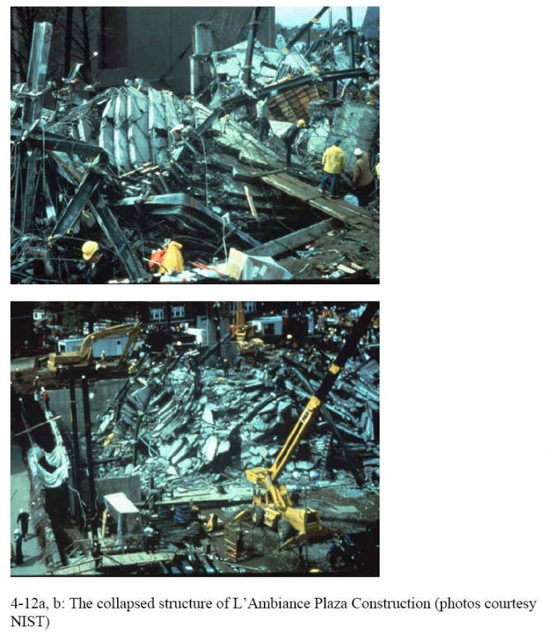
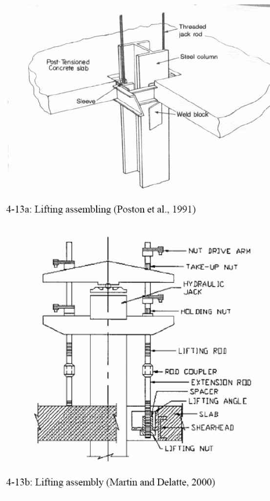
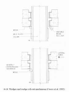
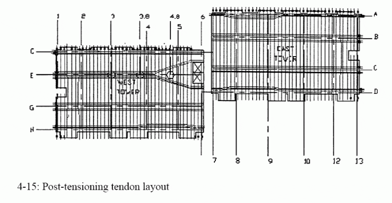
Also – see the Cleveland Lift-Slab Parking Garage
New York Coliseum
At the New York Coliseum in 1955 (McKaig 1962, Kaminetzky 1991) about 10,000 square feet of main exhibition hall collapsed during construction, killing one worker and injuring fifty others. The forms were two stories high, supported on 11-foot four-by-four timbers linked together by a cross beam at mid-height. The crossbeams did not provide bracing against lateral instability. Buggies were used to transport the concrete for the slab being poured, and eight buggies were on the formwork at the time of the collapse. According to the district attorney’s office, the cause of failure was inadequate provisions in the formwork to resist lateral forces (p. 16, McKaig, 1962). Without proper bracing, the structure became unstable under the dynamic loading of the buggies. Formwork designs that had been safe before the use of buggies proved unsafe under the heavier loads. McKaig (1962) also discusses fourteen other formwork failures.
References:
McKaig, T. (1962). Building Failures: Case Studies in Construction and Design. McGraw-Hill, New York, N. Y.
Kaminetzky, D. (1991). Design and Construction Failures: Lessons from Forensic Investigations. McGraw-Hill, New York, N. Y.
Oklahoma City Murrah Federal Building Bombing
Extreme events, such as earthquakes, test structures near their ultimate capacity and sometimes lead to destruction. Explosions, whether intentional or accidental, do the same thing. On April 19, 1995, a truck bomb tore through the facade of the Murrah Federal Building in Oklahoma City. The blast destroyed a significant portion of the structure, killing 169 people. This event was a classic example of what is known as progressive collapse.
Disproportionate collapse is now becoming the preferred term because all collapses are inherently progressive. What disproportionate collapse means is that an event that should have been localized to one part of the structure instead causes most or all of the structure to collapse, out of proportion to the original damage. It implies a lack of structural redundancy. Ronan Point is considered another case of disproportionate collapse.
The Murrah Building was designed in 1974 and opened three years later. It conformed to all of the structural codes of the time (Wearne 2000, p. 117). This case led to a shift in philosophy in structural design. Before this attack, it was generally thought that special detailing of reinforced concrete construction was necessary only in areas with significant seismic hazard.
Hinman and Hammond (1997, p. 34) recommended that reinforced concrete structures subject to blast and similar threats be designed and detailed with alternate load paths and with continuous top slab reinforcement. Columns, beams, and girders should have ties to confine the concrete and provide ductility. Reinforcement bars should be properly anchored. Essentially, seismic design and detailing should be used to provide structural ductility and redundancy.
One key reference is Osteraas (2006). The comprehensive work on the engineering aspects of the Oklahoma City bombing attack is Lessons from the Oklahoma City Bombing: Defensive Design Techniques, written by E. E. Hinman and D. J. Hammond (1997). This document has become an important reference for developing building designs that are more resistant to this type of attack. The case is also discussed in Chapter 6 of Wearne (2000, pp. 117-135).
Hinman, E. E., and Hammond, D. J. (1997). Lessons from the Oklahoma City Bombing, Defensive Design Techniques, ASCE Press, New York.
Osteraas, J. D. (2006). “Murrah Building Bombing Revisited: A Qualitative Assessment of Blast Damage and Collapse Patterns,” J. Perf. of Constr. Fac., 20(4), 330-335.
Wearne, P. (2000). Collapse: When Buildings Fall Down, TV Books, L.L.C. (www.tvbooks.com), New York. (This book is a companion to The Learning Channel’s television series “Collapse.”)
Illustrations from Chapter 5 of the book Beyond Failure: Forensic Case Studies for Civil Engineers, Delatte, Norbert J., ASCE Press.
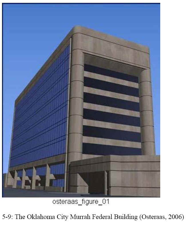
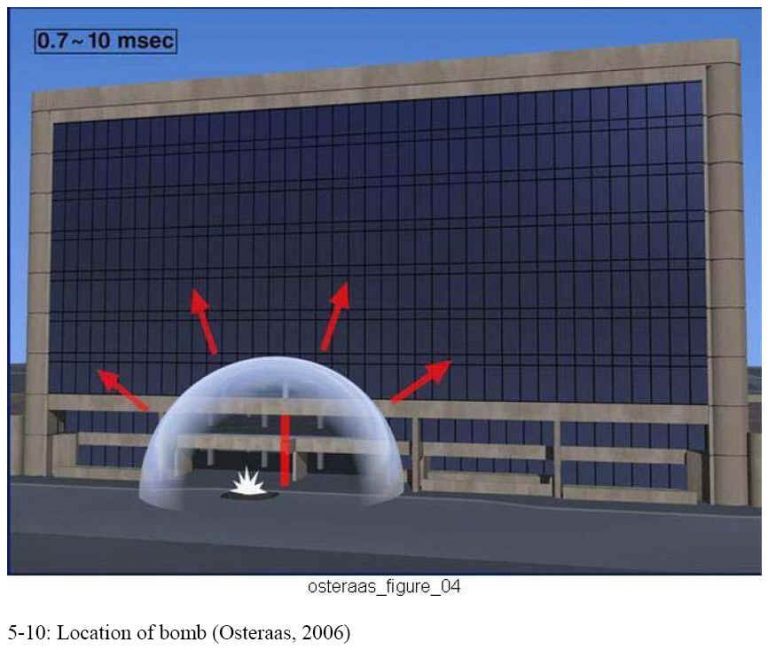
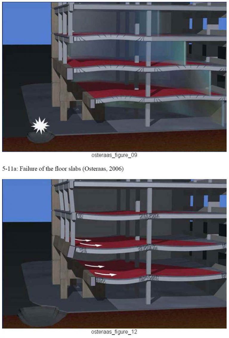
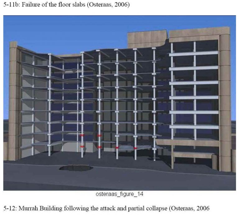
Pentagon Attack, September 11, 2001
The Pentagon terrorist attack of September 11, 2001, provides another case study of reinforced concrete building performance under extreme loading. The Pentagon performed quite well during the event, and as a result, the damage was localized to the area of immediate impact.
At 9:38 a.m. on September 11, 2001, a hijacked Boeing 757-200 airliner was deliberately crashed into the building. The impact hit the building about 43 m (140 ft) to the south of a boundary between the renovated section of the building and the next section scheduled for renovation. The aircraft continued into the section not yet renovated. The impact and fire killed the 64 people aboard the aircraft and 125 people in the building (Mlakar et al. 2003, p. 4).
Part of the building in the renovated section to the south of the expansion joint subsequently collapsed about 20 min after the aircraft struck the building. Photos taken between the aircraft impact and the collapse show that this portion of the building was sagging by about 0.45-0.6 m (1 1/2-2 ft). All five floors of the building collapsed. Some of the blast-resistant windows stayed in place even after the collapse. The collapse was confined to the outer E ring (Mlakar et al. 2003, pp. 17-26). Figure 5-13 shows the building after the collapse of the portion adjacent to the expansion joint.
The comprehensive work on the engineering aspects of the Pentagon on September 11, 2001, is The Pentagon Building Performance Report by the Pentagon Building Performance Study Team (Mlakar et al. 2003). The case is also featured in five papers published in the proceedings of ASCE’s Third Forensic Congress (Bosela et al. 2003).
Illustrations from Chapter 5 of the book Beyond Failure: Forensic Case Studies for Civil Engineers, Delatte, Norbert J., ASCE Press.
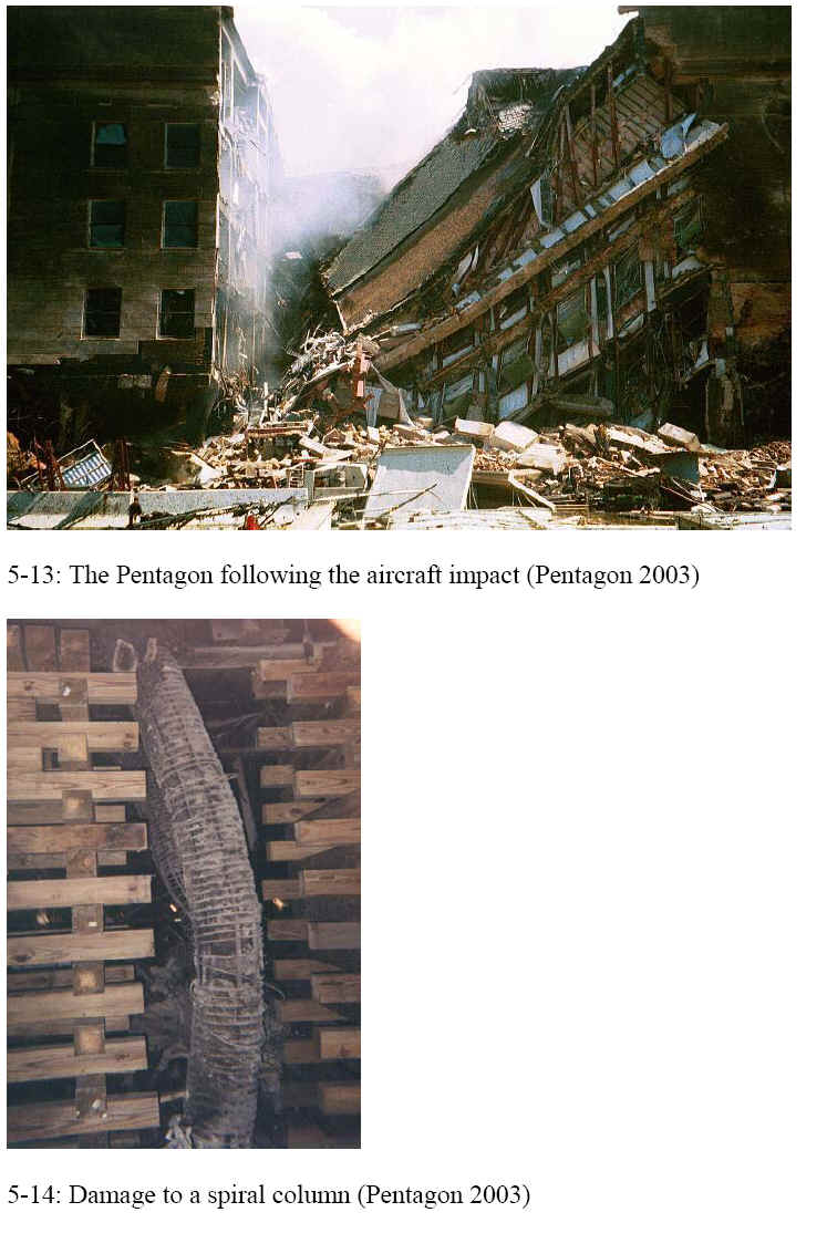
Pittsburgh Convention Center
The David L. Lawrence Convention Center in downtown Pittsburgh was built between 2000 and 2003 for the Sports & Exhibition Authority of Pittsburgh and Allegheny County, or SEA. It is a four-level structure, roughly 265-174 m (870- 570 ft) in the plan. An expansion joint along column line X9, roughly 146 m (480 ft) from the west end, splits the center approximately in two. The connections of the expansion joint are exposed to ambient temperatures (WJE 2008).
At about 1:30 p.m. on Monday, February 5, 2007, a tractor-trailer was parked on the second-floor loading dock of the convention center. The trailer had just hitched its bumper to the loading dock. Under the weight, a 6.1 -18 m (20-60 ft) section o the concrete slab and the steel beam supporting it collapsed. There were, fortunately, no injuries. The ambient temperature at the time was about -19 to -14 C (-3 to -7 F). Problems with 18 misaligned portions of the column foundations had halted construction work in November 2001, and the collapse had occurred in the vicinity of the shifted columns. Work was resumed once repairs had been made to some precast concrete beams. The $370 million building opened in 2003. The collapse led to the cancellation of the Pittsburgh International Auto Show (Ritchie and Houser 2007, WJE 2008).
At the time, a reporter for the Pittsburgh Tribune-Review, Mark Houser, called me and sent me a picture of the collapse and asked for comment. From the photo, it was difficult to attempt to figure out what was going on. He noted, however, that the failure had occurred at an expansion joint. Because it had been a cold day, it was possible that the expansion joint detail had played a role. In the newspaper article, I observed,
If you have a bolt holding something on, and it contracts due to cold then you come along and load it up, the combination of the two may be enough to cause a failure where neither one by itself would. An expansion joint will be open the most when it’s coldest. The more an expansion joint opens up, the harder it’s going to be to hold up the gravity load. And at some point, if an expansion joint opens up too much, it may actually slip off (its support) (Ritchie and Houser 2007).
It was, of course, a somewhat wild but educated guess based on limited information. However, the investigation determined that the expansion joint was in fact the culprit.
This partial collapse was, on the whole, a relatively minor and local case. However, it illustrates the principle that many useful failures and near-failure case studies can be found in the newspaper every year. This expansion joint failure occurred near the start of a course on strength of materials that I was teaching, and the newspaper article handouts provided useful material for classroom discussions. A recent connection failure is of more direct interest to students than the case of the Hyatt Regency walkways, which is now approaching three decades old.
The Wiss, Janney, Elstner Associates, Inc., final report can be found on-line at http://www.pgh-sea.com/images/DLLCCCollapseFinalReportFeb%2008.pdf.
Pittsburgh Midfield Terminal Precast Beam Collapse
Unless a sufficient development length of steel is embedded in concrete, the bar will pull out before it yields. In 1990 a portion of the Pittsburgh Midfield Terminal failed during construction. In a precast concrete beam, the bottom reinforcing bar was embedded only 185 mm (7 inches), which is much shorter than necessary (Thornton and DeScenza 1997).
Reference:
Thornton, C. H., and DeScenza, R. P. (1997). Construction Collapse of Precast Concrete Framing at Pittsburgh’s Midfield Terminal. Forensic Engineering: Proceedings of the First Congress, K. L. Rens, ed., ASCE. New York, N. Y. 85-93.
Sampoong Superstore
The collapse of the Sampoong Superstore in Seoul, South Korea, represents an example of a structural collapse attributed in large part to corruption.
The Sampoong department store opened in December 1989. It was a nine-story building with four basement floors and five above grade. The building was laid out in two wings (north and south) connected by an atrium lobby. By the mid-1990s the store’s sales amounted to more than half a million U.S. dollars a day (Wearne 2000, pp. 99-100).
Unfortunately, the store had been built on a landfill site that was poorly suited to such a large structure. Woosung Construction built the foundation and basement and then passed the project onto Sampoong’s in-house contractors. Woosung had apparently resisted some proposed changes to the building plans, such as the addition of the fifth floor (Wearne 2000, p. 100).
Sampoong made significant changes to the structure. The most important were the conversion of the original use as an office block to that of a department store. Other changes included changing the upper floor from a roller-skating rink to a traditional Korean restaurant. Stricter standards had to be met for fire, air conditioning, and evacuation. Although the structure apparently met all building code requirements, the revised design was radically different from the original (Wearne 2000, p. 100).
The building was put into service.
“For five and a half years business thrived. In June 1995 the store passed a regular safety inspection. But within days there were signs something was seriously wrong: cracks spidering up the walls in the restaurant area; water pouring through crevices in the ceiling. On June 29 structural engineers were called in to examine the building. They declared it unsafe. Company executives who met that afternoon decided otherwise. They ordered the cracks on the fifth floor to be filled and instructed employees to move merchandise to the basement storage area “(Wearne 2000, p. 100).
Some employees heard rumors of the structural damage and impending collapse but remained in their departments to work. At 6:00 p.m. on June 29, the center of the building collapsed, similar to a controlled implosion, in about 10 s. The five-story north wing, about 91 m (300 ft) long, fell into the basement, leaving only the facade standing (Wearne 2000, pp. 100-102).
Customers were concentrated in the basement and in the fifth-floor restaurant. The customers and employees had no time to run. Some survivors were found in the wreckage, and one was brought out 17 days after the collapse. The overall death toll was 498 (Wearne 2000, pp. 100-107).
The final report was delivered by the Seoul District Prosecutors Office, entitled The Final White Book of Finding Out the Real Truth of the Collapse of the Sampoong Department Store. The public was outraged. In particular, the news that the senior executives had fled the building without warning others was disturbing. The report on the collapse, as well as earlier structural and construction failures, suggested a widespread pattern of corruption in the country’s construction business. A government survey of high-rise structures found 14% were unsafe and needed to be rebuilt, 84% required repairs, and only 2% met standards. Joon Lee, the chairman of Sampoong, and his son Han-Sang Lee were convicted and sent to prison for 10 1/2- and 7-year terms, respectively. Twelve local building officials were found guilty of taking bribes of as much as $17,000 (U.S. equivalent) for approving changes and providing a provisional use certificate (Wearne 2000, pp. 111-112).
The cause of the Sampoong collapse, then, was not a technical issue as much as outright fraud. The Korean construction industry, protected by government regulation from outside competition, had become complacent. Bribes were used to get around the usual government checks and balances that serve to protect public safety.
This case study is discussed in chapter 10 of the book Beyond Failure: Forensic Case Studies for Civil Engineers, Delatte, Norbert J., ASCE Press. This case study is discussed by Wearne (2000, pp. 99-113) in Chapter 5, entitled Crooked Construction: Sampoong Superstore. A technical paper on the collapse entitled Lessons from the Sampoong Department Store Collapse (Gardner et al. 2002) was published in the Cement & Concrete Composites journal.
Wearne, P. (2000). Collapse: When Buildings Fall Down, TV Books, L.L.C. (www.tvbooks.com), New York. (This book is a companion to The Learning Channel’s television series “Collapse.”)
Steel Frame Connections in Northridge Earthquake
Many cases in structural engineering have illustrated the importance of careful attention to connections. The Northridge Earthquake of 1994 showed that the Special Moment Resisting Frame welded connection behaved much worse than anticipated during the event (four papers in Rens 1997, pp. 219-257). This is an excellent example of the dangers of extrapolating behavior from small test specimens to full-scale structures, and of why codes and standards continue to evolve.
References:
Four papers are provided in Rens, K. L., editor (1997). Forensic Engineering: Proceedings of the First Congress. ASCE. New York, N. Y.
The Ronan Point Apartment Tower Case
Summarized from Rouse and Delatte, Lessons from the Progressive Collapse of the Ronan Point Apartment Tower, Proceedings of the 3rd ASCE Forensics Congress, October 19 – 21, 2003, San Diego, California
Introduction
In the early morning hours of May 16, 1968, the occupant of apartment 90 on the 18th floor of the Ronan Point apartment tower lit a match for her stove to brew her morning cup of tea. The resulting gas explosion, due to a leak, knocked her unconscious.
The pressure of the small gas explosion blew out the walls of her apartment and initiated a partial collapse of the structure that killed four people and injured seventeen. The partially collapsed structure is shown in figure 4-5, and the floor plan for Apartment 90 is provided in figure 4-6.
Design and Construction
Many high-rise apartments were constructed in London to replace the housing stock destroyed during the Second World War. During this time, a change in national policy allowed the density of occupancy to double. Skilled construction laborers were also becoming scarce. This shortage began as workers began to take safer and easier jobs in factories (Bignell 1977). These reasons and the development of prefabricated construction techniques (known as system building) led to the popularity of high-rise apartment buildings. This new style of housing could accommodate large numbers of people, save land and labor, and be constructed quickly.
The Ronan Point Apartment Tower was constructed using the Larsen-Neilsen system. This system was developed in Denmark in 1948. The Larsen-Nielson system was composed of factory-built, precast concrete components designed to minimize on-site construction work. Walls, floors, and stairways are all precast. All units, installed one-story high, are load bearing (System, 1968).This building technique encompassed the patterns for the panels and joints, the method of the panel assembly, and the methods of production of the panels.
Ronan Point was the second of nine identical high-rise precast concrete flat plate structures that were erected in London after the war. In this type of structural system, each floor was supported by the load bearing walls directly beneath it. Gravity load transfer occurred only through these load-bearing walls. This wall and floor system fitted together in slots. These joints were then bolted together and filled with dry pack mortar to secure the connection. The connections are shown in figures 4-7 and 4-8.
Ronan Point was twenty-two stories tall. There were a total of 110 apartments units in the building, grouped five to a floor. The total number of units comprised forty-four two-bedroom apartments and sixty-six one-bedroom apartments. Construction began on Ronan Point on July 25, 1966, and was completed on March 11, 1968 (Cook 2002). Construction took less than two years and the building was at near full occupancy for less than three months before a section of it collapsed.
Collapse
The southeast corner of the Ronan Point Tower collapsed on May 16, 1968, at approximately 5:45 a.m. Four people died and seventeen were injured. The fatality rate could have been considerably higher given the extent of the structural damage (Feld and Carper 1997). Fortunately, at the time of the disaster, all of the residents but one were sleeping in their bedrooms. The collapse sheared off the living room portion of the apartments, leaving the bedrooms intact with the exception of floors seventeen through twenty-two, where all the fatalities occurred. This corner of the building contained the only three vacant apartments left in the building. The apartment on floor twenty-two was the only one occupied above floor eighteen.
The collapse was initiated by a gas-stove leak on the eighteenth floor in apartment ninety. The resident struck a match to light the stove to make a cup of tea and was knocked unconscious by the resulting explosion. The force of the explosion knocked out the opposite corner walls of the apartment. These walls were the sole support for the walls directly above. This created a chain reaction in which floor nineteen collapsed, then floor twenty and so on, propagating upward. The four floors fell onto level eighteen, which initiated the second phase of progressive collapse. This sudden impact loading on floor eighteen caused it to give way, smashing floor seventeen and progressing until it reached the ground.
Causes of Failure
Pressured by the public, the government formed a panel to investigate the collapse. The panel’s report was issued later that year (Griffiths et al., 1968). It was quickly determined the explosion from the gas leak had initiated the collapse of the building. A substandard brass nut had been used to connect the hose to the stove. The nut had a thinner flange than the standard, and also had an unusual degree of the chamfer. A replicate of this nut was made and tested to determine how much force was required to break it in tension.
It was concluded that a force of 15.6 kN (3,500 pounds) would break the connection. It was also concluded that the hose connecting the stove to the gas would have failed before the nut at a force of 1.6 kN (360 pounds). The nut was assumed to have been previously fractured by over-tightening during installation, causing it to break, allowing gas to leak into the apartment (Griffiths et al., 1968).
The gas may have accumulated at the ceiling, explaining why the resident did not detect it. The explosion was not significant in terms of magnitude. The residents hearing had not been damaged. This suggested that the pressure was less than 70 kPa (10 psi) (Bignell 1977). Items were taken from the kitchen of this apartment and tested. Results indicated that these objects had been exposed to pressures of less than 70 kPa (10 psi).
The Building Research Station and Imperial College of London performed an extensive battery of tests to discover how much internal force Ronan Point could withstand. The results indicated that the walls could have been displaced by a pressure of only 19.3 kPa (2.8 psi) (Levy 1992). It was estimated that the kitchen and living room walls were moved at a pressure of only 1.7 kPa (0.25 psi), while the exterior wall was moved at a gas pressure of 21 kPa (3 psi) (Griffiths et al., 1968).
Ultimately, the collapse of Ronan Point was due to its lack of structural redundancy. It had no fail-safe mechanisms, and no alternative load paths for the upper floors should a lower level give way. Without any type of structural frame, the upper floors had no support and fell onto floor seventeen. The panels forming floor seventeen could not support the sudden loading caused by the upper five floors that fell on it. Consequently, they gave way, and the process continued until it reached the ground level.
The southeast corner of Ronan Point was rebuilt as a separate section of apartments and then joined to the existing building by means of walkways. Ronan Point was reinforced with blast angles as part of the reconstruction. Gas was also banned from Ronan Point.
Technical Aspects
Several factors became apparent after the public inquiry into the collapse. The inquiry revealed that strong winds and/or the effects of a fire of the building could also have caused a progressive collapse. Ronan Point was designed to withstand wind velocities of only 100 kph (63 mph). A wind of 170 kph (105 mph) could be expected to occur at two hundred feet above the ground every sixty years, within the life expectancy of the building.
The building code used for the design of Ronan Point and its sister buildings was issued in 1952. This set of codes had not been kept up to date. Higher than stated winds were known to occur based on a publication in 1963 by the National Physical Laboratory (Griffiths et al., 1968). It was noted that the structure had been designed to comply with fifteen-year-old wind load codes that did not take into account current building heights (Britain 1970). According to the inquiry, the suction effect of the pressures applied by such winds, in particular, the opening of the joints as the tower block bent in the wind, would have a similar effect to the explosion.
The fire also would have had a similar effect on Ronan Point. The inquiry stated, it is estimated that fire could so expand and arch the floor slab and bend the wall panel, as to displace or rotate an H-2 joint to a dangerous degree.(Wearne, 2000).
Upon architect Sam Webbs recommendation, a fire test was conducted sixteen years after the collapse of the southeast corner, which verified this theory. Webb had followed the issues concerning Ronan Point since its partial collapse. He predicted that after approximately fifteen years of service, Ronan Point would develop serious structural problems, especially in the joints. In a conversation with some tenants of Ronan Point he stated, there would be gaps between walls and floors through which smoke would pass; that you’d be able to hear people and their television on different floors.
Some of the residents invited him into their apartments to perform some simple tests. According to Webb, One of the simplest tests was to get a sheet of paper, tear a strip off, put it against the skirting board, and let it go at one end. The loose end was coming out at ceiling level in the apartment below. Another basic test was to put a coin up against the wall and let it go. It fell through the gap as if going into a slot machine. (Wearne, 2000).
The chair of Newham’s Housing Committee asked Webb to conduct a survey to assess the condition of the building. He and a team of architectural students surveyed nearly half of Ronan Point one hundred ten apartments. Their findings revealed cracks in the central stairwell and elevator shaft, which indicated movement throughout the building. After analyzing the cracks, Sam Webb realized that his predictions about Ronan Point had been confirmed. He concluded, In high winds, it was beginning to break up. The building was moving on its lifting bolts and was held up by the blast angles fitted after the public inquiry. The dry pack mortar had been crushed or was never there in the first place.(Wearne, 2000).
Continuing concerns over the building’s structural integrity eventually led to its demolition in May of 1986. This type of building had a life expectancy of sixty years. Ronan Point was razed after just eighteen years of service. However, the building was not demolished in the traditional fashion. Webb suspected poor workmanship and therefore insisted that Ronan Point is dismantled floor by floor so that the joints could be studied. The site was an open site for anyone interested. It was verified that compromises in workmanship were present.
A shocked Webb commented, I knew we were going to find bad workmanship what surprised me was the sheer scale of it. Not a single joint was correct. Fixing straps were unattached: leveling nuts were not wound down, causing a significant loading to be transmitted via the bolts: panels were placed on bolts instead of mortar. But the biggest shock of all was the crucial H-2 load-bearing joints between floor and wall panels. Some of the joints had less than fifty percent of the mortar specified. (Wearne, 2000).
Professional and Procedural Aspects
The findings of such magnitude of poor workmanship performed in the construction of Ronan Point led to the demolition of the remaining Larsen Nielson system built towers. At the time these buildings were erected, the building codes did not adequately address them. Large concrete panel construction was the height of innovation at this time, and little was known about how it would perform. The building regulations in effect at the time contained a catch-all clause known as the functional requirement on the structure. This clause contained no mention of redundancy or progressive collapse (Bignell 1977).
The collapse of the southeast corner of Ronan Point initiated changes to the regulation codes. Building codes now take in account for the possibility of progressive collapse and of forces from an internal explosion. The codes also require minimum amounts of ductility and redundancy.
One of the outcomes of this inquiry was the development of the Fifth Amendment to the English building regulations in 1970. According to Arnold W. Hendry, it applies to all buildings over four stories and requires that under specified loading conditions a structure must remain stable with a reduced safety factor in the event of a defined structural member or portion thereof being removed. Limits of damage are laid down and if these would be exceeded by the removal of a particular member, that member must be designed to resist a pressure of 34 kN/m (51 lb/in) from any direction. Of special importance in relation to load bearing wall structures are that these conditions should be met in the event of a wall or section of a wall being removed, subject to a maximum length of 2.25 times the story height.(Hendry, 1979).
The British also conducted their own research on progressive collapse. The United States followed and also implemented new design criteria (Fuller 1975). The lesson from Ronan Point changed building regulations throughout the world.
The government mandated guidelines for the prevention of progressive collapses. These instructions included the requirement a fail-safe mechanism in all large panel system buildings, steel bracing with floor to wall connectors, and a minimum tensile strength of 21 MPa (3000 psi) across the length and width of the roofs and floors (Britain, 1970).
The Portland Cement Association and the Prestressed Concrete Institute also issued their own set of guidelines. These methods called for tying building elements together and increasing ductility so that the building elements can better sustain deformations from the failure of a portion of the structure of the building. Transverse ties create cantilever action from adjacent walls. Vertical ties provide suspension from panels above, peripheral ties hold floors together, and longitudinal ties string floor planks-large prestressed panels-together (Ross 1984).
The engineering profession was reminded of the need for redundancy in design to prevent a progressive collapse. It is of utmost importance that building designs contain some measure of continuity (Shepherd and Frost, 1995). Extensive research was carried out in the United Kingdom to provide engineers and architects with data for load bearing walls. When the Larsen Nielson system was developed, it was not intended to be used in buildings of more than six floors. However, in the U.K. it was used for taller structures.
It was concluded by the inquiry that the codes governing construction and design methods needed immediate reevaluation. The authors of the inquiry stated this in their report we do not consider that in its present form Ronan Point is an acceptable building, and yet it was designed to comply with the statutory standards contained in the Newham by-laws, which are, in all material respects, identical with current Building Regulations. This is so manifestly an unsatisfactory state of affairs that it is necessary to enquire how it came about and to consider remedies for the future(Griffiths et al., 1968).
The concept of quality control in the construction process was recognized after the dismantling of Ronan Point. Although the design flaw was the primary downfall of Ronan Point, poor construction quality could have led to future problems with the buildings structural integrity. It is imperative that quality control is enforced in the construction process to ensure public safety. According to Feld and Carper (1997), As with all other construction materials, the best designs in precast and prestressed concrete can be ineffective unless the work done in the field is of high quality. If the design is marginal, construction deficiencies can compound the errors increasing the potential for serious problems Skilled supervisors who understand the design intent and can communicate it clearly to the field workers are needed full-time at the construction site while all prestressed concrete work is erected. (Feld and Carper, 1997).
Ethical Aspects
Substandard workmanship had been detected in the initial inquiry of the collapse. Even though it was determined to be a negligible factor in the corner collapsing, this information was hidden from the public. Was it a question of ethics or politics? By the time the inquiry’s findings were published in 1968, many large panel concrete buildings had been completed. This was the government’s method of keeping its promise of housing the numbers of people living in slums after the war had demolished a quarter of the homes in England. The government did not want to consider demolishing these buildings. At least six Larsen-Nielson system buildings had been completed by this time. There was not enough money to strengthen them. So the question is, did the government endanger the lives of the residents of these facilities by taking only minimal action to strengthen the buildings?
Webb was very active in taking measures to inform the public of the possible hazards associated with these types of buildings. He made officials aware of possible dangers that could lead to another progressive collapse such as high winds, or a building fire. He was a strong advocate of demolishing these death traps.
Educational Aspects
There are many lessons to be learned from this case. This is an excellent example of what could happen when an alternative load path is not provided. Some classroom calculations related to this case may include the removing of both horizontal and vertical members, one at a time, and calculating the redistributed forces, to see how a multistory large panel building would react to a missing member. Students can learn from this case the importance of building codes and monitoring construction quality.
Summary and Conclusions
The investigations found that the Ronan Point apartment tower was deeply flawed in both design and construction. The existing building codes were inadequate for ensuring the safety and integrity of high-rise precast concrete apartment buildings. In particular, the design wind pressures were too low and did not account for the height of the building. The Larsen Nielson building system, intended for buildings with only six stories, had been extended past the point of safety.
The tower consisted of precast panels joined together, without a structural frame. The apartment tower lacked alternate load paths to redistribute forces in the event of a partial collapse. When the structure was dismantled, investigators found appallingly poor workmanship of the critical connections between the panels. The already shaky structure had been further weakened by the inadequate construction practices. The result was described by Levy and Salvadori (1992) as a house of cards.
The relatively low overpressure from the gas explosion should have led to localized damage at most, not a partial progressive collapse and the loss of four lives. The evaluation also found that the building was unusually vulnerable to ordinary wind and fire loading.
Print References
Bignell, Victor; Peters, Jeoff; Pym, Christopher. (1977). Catastrophic Failures. Open University Press, Milton Keynes, New York.
Britain. (1970). Britain tightens building standards, moves to stern progressive collapse. Engineering News-Record. April 16, 1970, 12.
Feld, Jacob, and Carper, Kenneth (1997). Construction Failure. John Wiley and Sons, Inc., USA.
Fuller, Robert (1975). Industrialized concrete Construction for HUD. Industrialization in Concrete Building Construction. American Concrete Institute, Detroit, Michigan USA.
Griffiths, Hugh; Pugsley, A. G.; Saunders, Owen, (1968). Report of the Inquiry into the Collapse of Flats at Ronan Point, Canning Town. Her Majestys Stationery Office, London.
Hendry, Arnold, W. (1979). Summary of Research and Design Philosophy for Bearing Wall Structures. Journal of the American Concrete Institute. 76(33), 723-737.
Levy, Matthys and Salvadori, Mario, (1992). Why Buildings Fall Down. W.W. Norton and Company, New York, New York.
Ross, Steven (1984). Construction Disasters: Design Failures, Causes, and Prevention. An Engineering News-Record Book. McGraw-Hill Book Company, USA.
Shepherd, Robin, and Frost, J. David (1995). Failures in Civil Engineering, Structural, Foundation and Geoenvironmental Case Studies. American Society of Civil Engineers, New York, New York.
Systems. (1968). Systems Built Apartments Collapse.Engineering News-Record. May 23, 1968, 23.
Wearne, Phillip (2000). Collapse: When Buildings Fall Down. TV Books, L.L.C., USA.
Web References and Ronan Point Web Sites
https://www.open2.net/modernity/3_13.htm
http://www.lalamy.demon.co.uk/ronanpnt.htm
https://www.open2.net/modernity/2_5_3.htm
https://www.steelbreeze.fsnet.co.uk/disaster/680516.html
https://www.cen.bris.ac.uk/civil/staff/dib/casehist99/ronanpoint.htm
http://www.waltersforensic.com/civil/vol5-no2.htm
http://www.skyscrapers.com/re/en/im/df/142817/
http://www.nibs.org/MMC/ProgCollapse%20presentations/Cagley%20paper.pdf
http://www.muswell-hill.com/foxandco/pages/corgi.htm
http://www.museum-london.org.uk/MOLsite/exhibits/towerb/towerb.htm
Illustrations from Chapter 4 of the book Beyond Failure: Forensic Case Studies for Civil Engineers, Delatte, Norbert J., ASCE Press.
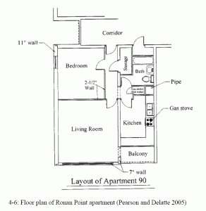
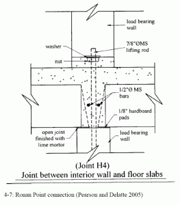
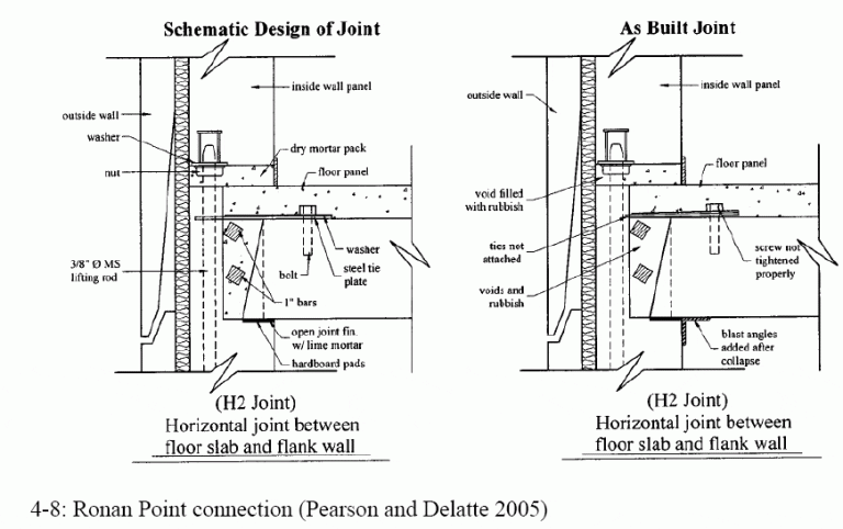
World Trade Center Attack, September 11, 2001
The collapse of the twin World Trade Center (WTC) towers on September 11, 2001, provides some insight into the vulnerabilities of steel structures against such attacks. After the event, the Federal Emergency Management Agency (FEMA) conducted an investigation (2002).
The FEMA BPS team made some general observations, findings, and recommendations based on the study of WTC-1 and WTC-2, as well as the other nearby structures:
- ” Structural framing systems need redundancy and/or robustness so that alternative paths or additional capacity are available for transmitting loads when building damage occurs.
- ” Fireproofing needs to adhere under impact and fire conditions that deform steel members so that the coatings remain on the steel and provide the intended protection.
- ” Connection performance under impact loads and during fire loads needs to be analytically understood and quantified for improved design capabilities and performance as critical components in structural frames.
- ” Fire protection ratings that include the use of sprinklers in buildings require a reliable and redundant water supply. If the water supply is interrupted the assumed fire protection is greatly reduced.
- ” Egress systems currently in use should be evaluated for redundancy and robustness in providing egress when building damage occurs, including the issues of transfer floors, stair spacing and locations, and stairwell enclosure impact resistance.
- ” Fire protection ratings and safety factors for structural transfer systems should be evaluated for their adequacy relative to the role of transfer systems in building stability (FEMA 2002, pp. 8-1-8-2).
The Federal Emergency Management Agency published World Trade Center Building Performance Study: Data Collection, Preliminary Observations, and Recommendations, FEMA report No. 403 (FEMA 2002). This report is available online in PDF format at http://www.fema.gov/rebuild/mat/wtcstudy.shtm. In addition to providing a thorough discussion of WTC-1 and WTC-2, the report also discusses the performance of the other nearby buildings, such as WTC-7. Free printed copies of FEMA reports may be obtained directly from FEMA at www.fema.gov.
Illustrations from Chapter 6 of the book Beyond Failure: Forensic Case Studies for Civil Engineers, Delatte, Norbert J., ASCE Press.
