Dam Failure Case Studies
Austin (Pennsylvania) Dam
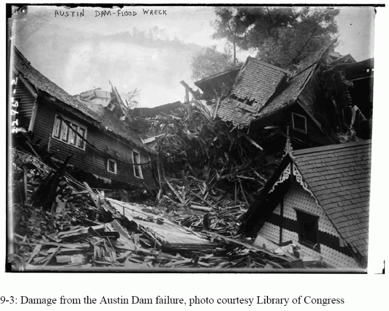
The quality of concrete construction is important, particularly in cold weather. The September 30, 1911, failure of a concrete gravity dam in Austin, Pennsylvania, claimed between 50 to 149 lives. Greene and Christ (1998) put the death toll at 78. It occurred less than 150 miles north of Johnstown, Pennsylvania, 22 years after that more widely known disaster (see Jamestown Flood).
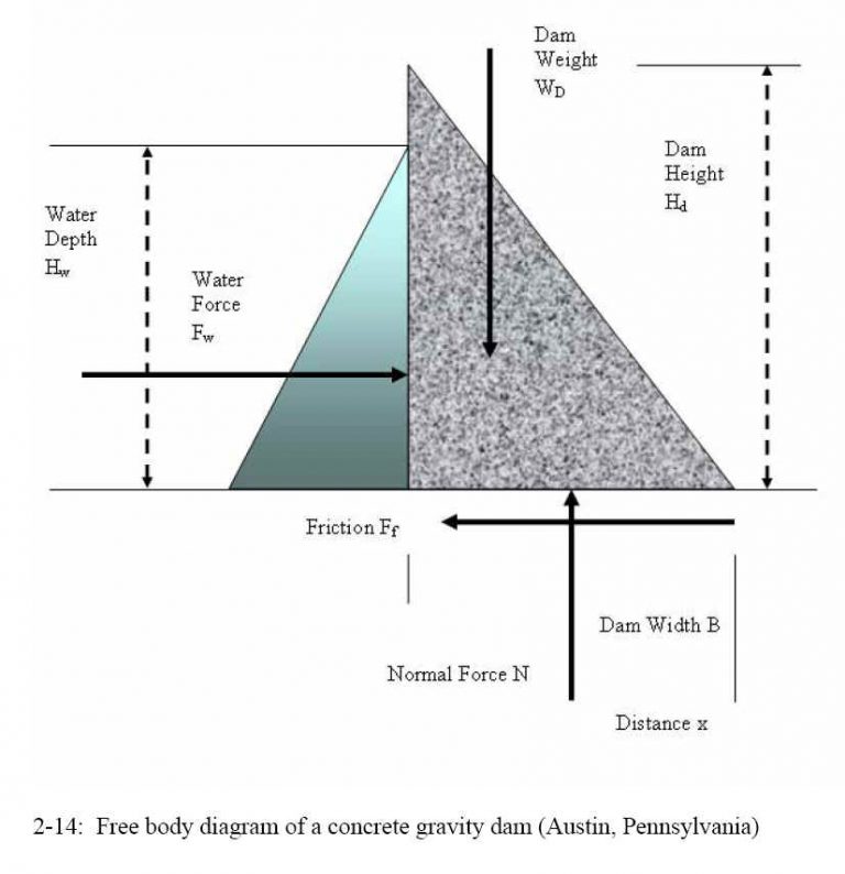
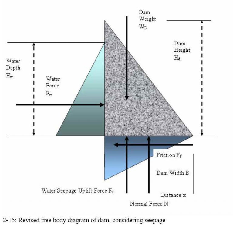
The Bayless Pulp and Paper Mill decided to replace a smaller dam with a larger dam in 1909 to increase production. The new dam was a gravity dam, designed to hold back the water by its mass and friction against the foundation. Cost and time constraints led to pressures to complete the dam before winter. The dam blocked the Freeman Run Valley and was 161 m (530 ft) long at the base and 166 m (544 ft) at the crest. The dam was 15 m (49 ft) high at the crest and 13 m (42 ft) high at the spillway, and 9.8 m (32 ft) thick at the base and 0.76 m (2.5 ft) thick at the crest. The reservoir filled half of the valley and was designed to hold 750,000 cubic meters (200 million gallons or 613 acre-feet) of water (Freiman and Schlager 1995b, pp. 205 -206).
The dam was built from 12,200 cubic meters (16,000 cubic yards) of cyclopean concrete. The cyclopean concrete consisted of boulder-sized pieces of native sandstone rock, bound with more conventional cement and concrete. Twisted steel rods 32 mm (1 in) in diameter, 7.6 m (25 ft) long, were spaced 0.8 m (2.7 ft) apart to reinforce the dam. An earth fill embankment 8.2 m (27 ft) high, sloped 3 horizontal to 1 vertical, was rolled against the upstream face of the dam (Freiman and Schlager 1995b, p. 207).
The dam’s foundation was the rock of the valley floor, which consisted of thin layers of shale between narrow layers of sandstone. About 6,000 cubic meters (8,000 cubic yards) of soil was excavated at the foundation, and loose material was washed and cemented together with grout. A 1.2 by 1.2 m (4 by 4 ft) footing extended into the bedrock, and the abutments were also cut 6.1 m (20 ft) into bedrock (Freiman and Schlager 1995b, p. 207).
The dam was not yet finished as winter approached, and the last hurried concrete construction was carried out with temperatures below freezing. By December 1, 1909, when the dam was completed, a large crack passed completely through the dam, fracturing some of the cyclopean boulders. A second crack appeared later that month. With the dam empty, and no visible settlement of the foundation, it appeared that the cause was a contraction of the concrete (Freiman and Schlager 1995b, pp. 207-208).
The dam reservoir was filled within about six weeks of completion. On January 17, 1910, a combination of heavy rain and snowmelt due to warm temperatures put flood water over the spillway. Heavy seepage near the toe of the dam and cracks on the downstream face of the dam was observed. To lower the reservoir, Bayless used dynamite to blast two notches in the dam crest. Superficial repairs were made to the dam after the water level dropped, and then the water level was allowed to rise to the normal pool again (Freiman and Schlager 1995b, p. 208).
During this event, the dam developed six prominent vertical cracks, and the top center of the dam bowed 0.76 m (30 in) downstream. The dam had been built without construction joints, so the cracks divided the dam into seven separate segments. The blasting had been necessary because the dam had no spillways or gates to allow controlled water release (Greene and Christ 1998, p. 9).
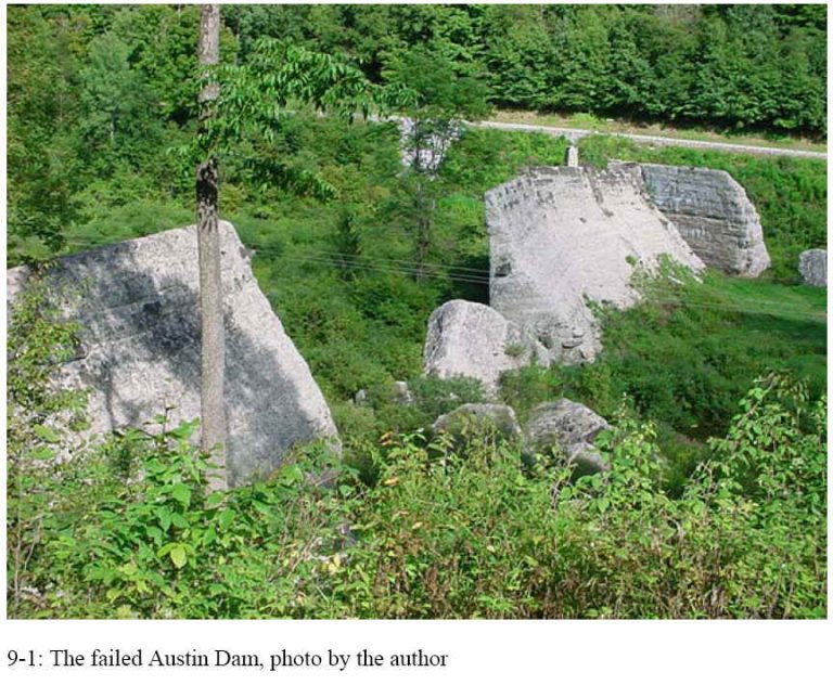
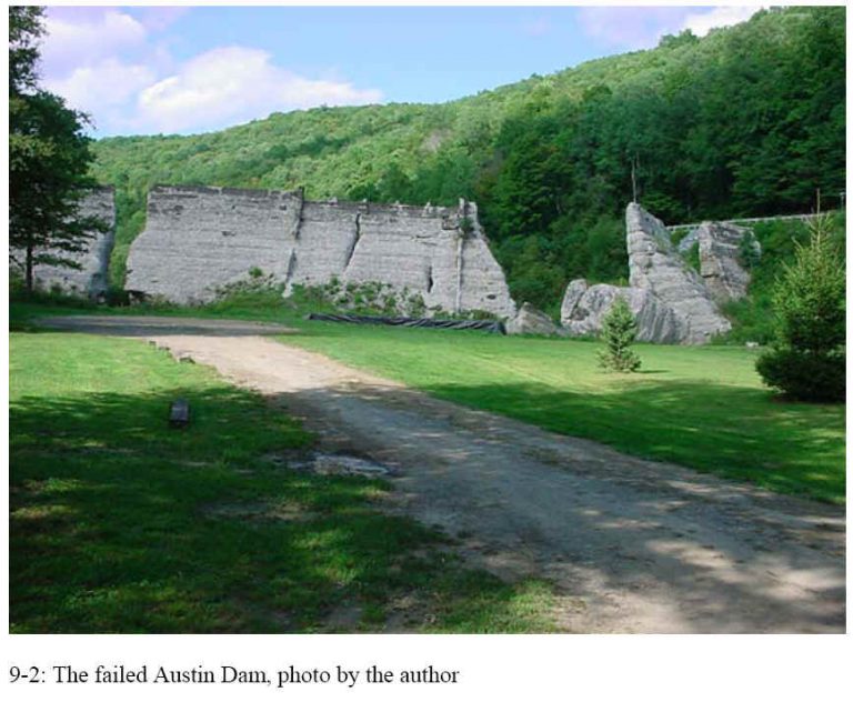
The dam failed on the afternoon of Saturday, September 30, 1911. A hole opened at the west abutment, and the force of the water pushed out the blocks of concrete which slid downstream. The water channeled as a large wave between the high vertical valley walls as it smashed into the town of Austin (Freiman and Schlager 1995b, p. 208).
Like the South Fork Dam responsible for the Johnstown Flood, the Austin Dam did not have pipes or any other means to rapidly reduce the water level in case of danger. The remains of the dam are still visible today along Pennsylvania Route 872, north of the town of Austin.
References and Sources
The complete case study is provided in Chapter 9 of Beyond Failure: Forensic Case Studies for Civil Engineers. This case is discussed by Freiman and Schlager (1995b, pp. 205 -212). Another source is Greene, B.H., and Christ, C.A. (1998), Mistakes of Man: The Austin Dam Disaster of 1911, published in Pennsylvania Geology.
Freiman, F.L., and Schlager, N. (1995b) Failed Technology: True Stories of Technological Disasters, Volume 2, UXL, Gale Research Inc., an International Thompson Publishing Company.
Greene, B.H., and Christ, C.A. (1998), Mistakes of Man: The Austin Dam Disaster of 1911, Pennsylvania Geology, Vol. 29, No. 2/3, pp. 7-14, Pennsylvania Department of Conservation and Natural Resources, Summer/Fall 1998, online at https://www.dcnr.state.pa.us/topogeo/pub/pageolmag/pageolonline.aspx
Illustrations from Chapters 2 and 9 of the book Beyond Failure: Forensic Case Studies for Civil Engineers, Delatte, Norbert J., ASCE Press.
Johnstown Flood
Johnstown, Pennsylvania, was a thriving community with a strong economy based on the coal and steel industries. The community was essentially wiped out by the historic Johnstown Flood of May 31, 1889, along with six other villages in the Conemaugh River Valley. The South Fork Dam, located 22 km (14 miles) upstream of the town, burst sending a wall of water approximately 12 m (40 ft) high at a speed of 32 kph (20 mph) down the valley. The debris from the flood was trapped against a surviving railroad bridge below the town and then caught fire. About three thousand died in the flood and fire, and thirty-five hundred were left homeless.
Construction of the South Fork Dam began in 1839 and was interrupted for ten years for lack of money. It was finally finished in 1853. The original purpose of the dam was to provide water for the Pennsylvania Canal running from Philadelphia to Pittsburgh. The original design included a spillway 45 m (150 ft) wide to allow water up to 3 m (10 ft) deep to pass safely over the dam.
Railroads became increasingly more important for transportation than canals, and four years after completing the dam was sold to the Pennsylvania Railroad. The railroad had little use for it, and the dam fell into disrepair. In 1880, the dam was sold to the South Fork Hunting and Fishing Club of Pittsburgh. Members of the club included Andrew Carnegie and Henry Clay Frick.
The new owners made dangerous modifications to the dam. The outlet pipes were removed since there was no longer a need to feed the canal. The dam was lowered 0.6 m (2 ft) and a trestle bridge for a road was installed across the spillway. A screen was placed in front of the trestle to keep fish from escaping from the reservoir if water overtopped the spillway. The spillway, a critical safety fuse to prevent the breach of any dam, was reduced to about a third of its capacity.
Heavy rain began on the evening of May 30. The clubs resident engineer, John G. Parke, Jr., observed the rising water in the morning and rode by horse to South Fork village and sent a warning telegram to Johnstown. He returned around noon, and found water already 2.25 m (7.5 ft) above normal lake level and cutting into the dam outer face. Parke ate lunch and then came back to the dam.
By this time, the water was washing away the outer face and cutting a large hole into the dam. The dam breached, and within 45 minutes the lake was fully drained. The rainfall was heavy about 127 mm (5 in) in 34 hours but the original spillway would have probably have been sufficient if the club had not made the modifications.
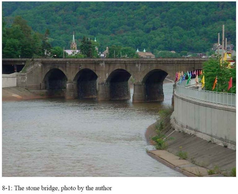
When the dam failed, the wall of water rolled down the Conamaugh River Valley and then smashed into Johnstown itself, where the Little Conamaugh River fed into Stony Creek, at roughly 4:07 p.m. It washed up into the hills and up Stony Creek and then washed back again. The destruction of the city took about ten minutes. Much of the debris became jammed at the Pennsylvania Railroad 7 m (23 ft) high stone bridge at the far end of the town. This formed a dam and kept the bulk of the water and debris from continuing on downstream. Some who were not drowned were pinned and buried in the debris pile, and perhaps eighty later died when the pile caught fire.
One important lesson from this disaster is the impact of land use on design and performance of engineered facilities. Two important changes which took place in the valley were the removal of timber from the hillsides, which dramatically increased runoff, and the tripling of the population following the Civil War. Very similar changes often take place with any dam project the land becomes more valuable, population increases (including downstream of the site), and forests are cleared and land is paved. These increase the extent of flooding as well as the potential property damage and loss of life. The U.S. has a vast dam infrastructure, much of which is poorly maintained. Critical elements to maintain are the safety valves the pipes and spillways.
The case study is covered in detail in Chapter 8 of Beyond Failure: Forensic Case Studies for Civil Engineers.
Essential Reading and Other Resources
The most important book on the disaster is The Johnstown Flood by David McCullough, D. (1968). McCullough includes extensive accounts of the individuals involved and was even able to interview some of the survivors decades after the disaster. Many of the survivors had left detailed personal accounts. This case is discussed by Levy and Salvadori (1992, pp. 162 -166).
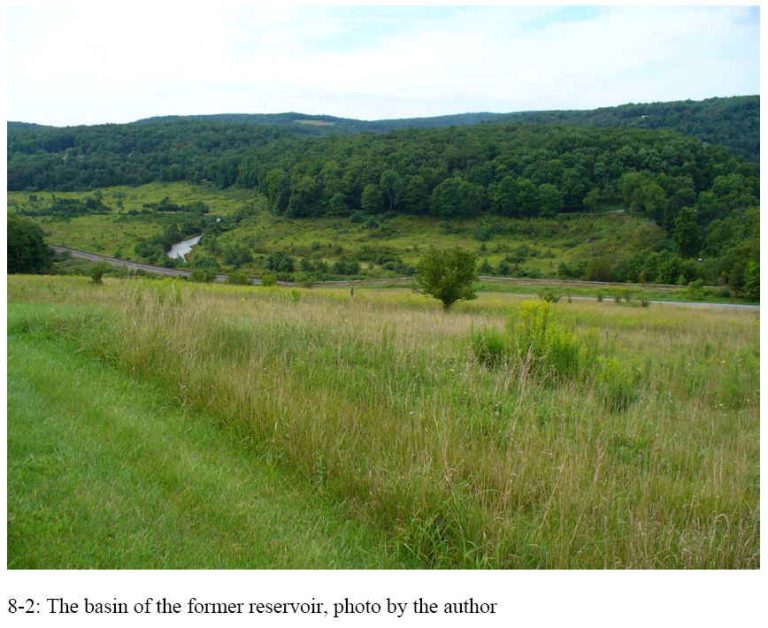
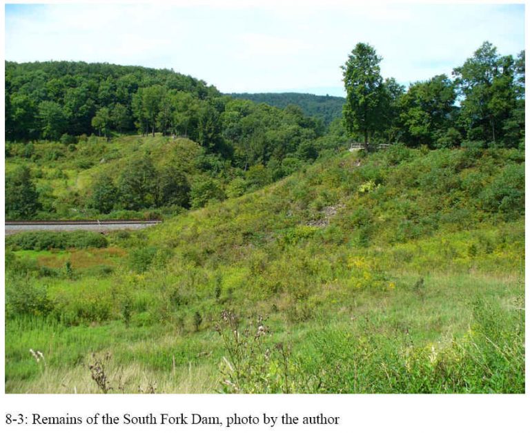
The Johnstown Flood is one of the few disasters of this type to be commemorated by a National Memorial operation by the National Park Service. The Johnstown Flood National Memorial (http://www.nps.gov/archive/jofl/home.htm) is located at the site of the failure of the South Fork Dam. The Memorial website states We encourage everyone who views this website to travel to the place where this event began, the South Fork Dam. The Johnstown Flood National Memorial preserves the remains of this dam and works with many area partners in order to tell you this story. The Johnstown Area Historical Association (https://www.jaha.org/) also maintains a Johnstown Flood Museum in Johnstown. Some photos from a visit to the South Fork Dam are shown below.
Illustrations from Chapter 8 of the book Beyond Failure: Forensic Case Studies for Civil Engineers, Delatte, Norbert J., ASCE Press.
Malpasset Dam Failure
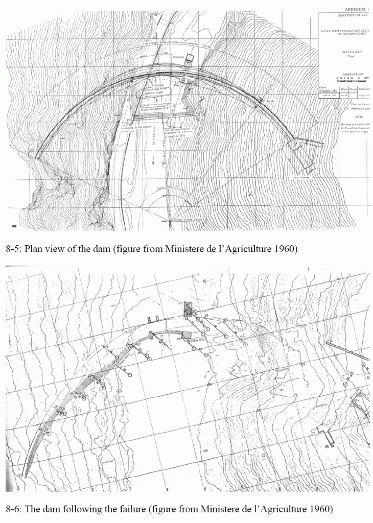
The sudden and unexpected collapse of the Malpasset Dam in France let to the considerable loss of life. This case study is discussed in Chapter 8 of the book Beyond Failure: Forensic Case Studies for Civil Engineers, Delatte, Norbert J., ASCE Press.
The Malpasset Dam was a continuation of the work of the famed designer Andr Coyne, who had slowly been raising the allowable compressive stresses within arch dams. At Malpasset, the allowable compressive stress was increased from 2.4 MPa (355 psi) to 4.7 MPa (680 psi). When it was completed, Malpasset was the thinnest arch dam in the world (Ross 1984, p. 127).
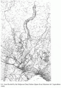
At 9:14 p.m. on December 2, 1959, the Malpasset dam failed explosively, giving rise to a flooding wave more than 40 m [130 ft] high. Only a little portion of the arch of the dam still remained in its original position. 421 casualties were reported.
The technical cause of the failure was revealed during the investigations. A thin clay filled seam in the rock behind the left abutment allowed the abutment to shift. This displacement and the loss of support led to the cracking at the center of the dam (Levy and Salvadori 1992, pp. 166-172).
The clay seam was only 25- 50 mm (1-2 inches) wide. The prosecutor, after the failure, alleged that this seam should have been taken into account in the design of the dam.
This case study is covered on pages 166-172 of Levy and Salvadori (1992). The French Ministry of Agriculture Final Report of the Investigating Committee of the Malpasset Dam (Ministere de l’Agriculture 1960) was published in English translation by the U.S. Department of the Interior and the National Science Foundation but may be difficult to find.
Illustrations from Chapter 8 of the book Beyond Failure: Forensic Case Studies for Civil Engineers, Delatte, Norbert J., ASCE Press.
New Orleans Hurricane Katrina Levee Failures
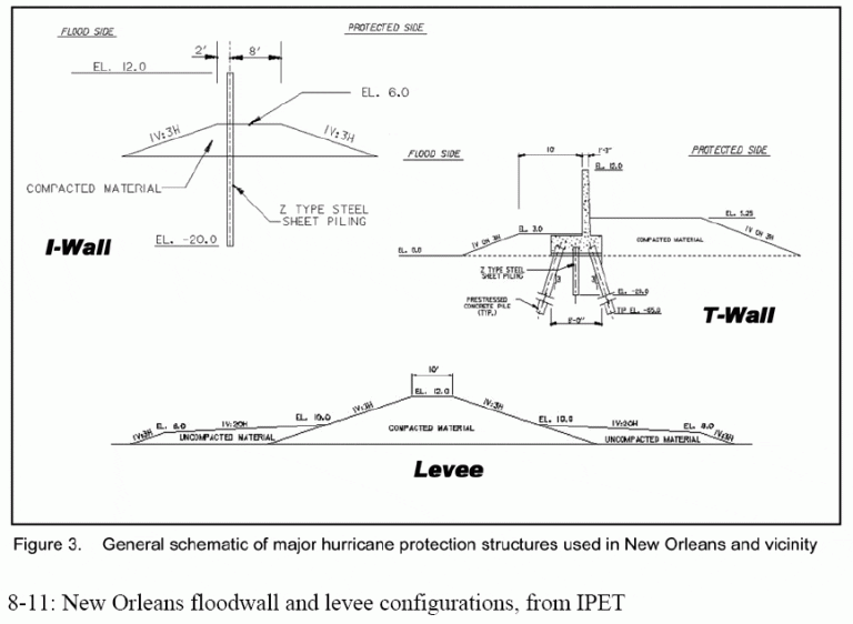
The failure of the levees and the flooding of New Orleans during Hurricane Katrina on August 29, 2005, represent the first time in history that an engineering failure has brought about the destruction or near-destruction of a major U.S. city. The ASCE Hurricane Katrina External Review Panel stated that
“The catastrophic failure of New Orleans’s hurricane protection system represents one of the nation’s worst disasters ever. A storm of Hurricane Katrina’s strength and intensity is expected to cause major flooding and damage. A large proportion of the destruction from Hurricane Katrina was caused not only by the storm itself, however, but also by the storm’s exposure to engineering and engineering-related policy failures” (ASCE Review Panel 2007, p. v).
Hurricane Katrina made landfall in the early morning of August 29, 2005, in southeast Louisiana to the east of New Orleans. Throughout the area, levees and flood walls failed or were breached in more than 50 locations. Eighty percent of the city of New Orleans was flooded, to a depth of more than 3 m (10 ft) in some neighborhoods. The extent of the destruction made it difficult to account for the victims, but the toll a year later was listed as 1,118 dead people and 135 missing and presumed dead. More than 400,000 citizens fled the city, many never to return. Property damage reached tens of billions of dollars (ASCE Review Panel 2007, p. 1).
Wind and storm surge are the damaging agents of a hurricane, storm surge at the coast and the wind away from the coast. Storm surge is a combination of wind-induced water motion, the reduced atmospheric pressure in the storm, and possibly high tide. Hurricane Katrina, unfortunately, came ashore at high tide, and the storm surge in Plaquemines Parish reached as much as 6.1 m (20 ft) above sea level. In Lake Pontchartrain, directly to the north of New Orleans, wind from the north piled water up as high as 3.7 m (12 ft) above sea level. The hurricane also brought heavy rainfall, increasing the probability of flooding (ASCE Review Panel 2007, pp. 13-16).
“The Lake Pontchartrain and Vicinity Hurricane Protection Project system experienced the worst damage during and after Hurricane Katrina and resulted in the most serious consequences to the city and people of New Orleans. The massive, destructive flooding of New Orleans was caused by ruptured at approximately 50 locations in the city’s hurricane protection system. Of the [457 km] 284 miles of federal levees and floodwalls-there are approximately [563 km] 350 miles in total-[272 km] 169 miles were damaged” (ASCE Review Panel 2007, p. 25).
Failures of the system began even before Hurricane Katrina made landfall, with overtopping of the Mississippi River-Gulf Outlet levees and flooding of parts of St. Bernard Parish. Shortly after landfall, at 6:30 a.m., levees on the south side of the New Orleans East neighborhood were also overtopped and breached. Shortly thereafter, waves reached 1.2 m (4 ft) in the Industrial Canal, causing more overtopping and flooding. Four I-walls also breached, between about 5:00 and 8:00 a.m., even before the water rose high enough to overtop them (ASCE Review Panel 2007, pp. 25-27).
With all of the breaches, some neighborhoods flooded to the rooftops in minutes. Even where the flooding was slower, further from the sites of the breaches, the water rose approximately 0.3 m (1 ft) every 10 min. The deadliest breaches were in the Industrial Canal and the London Avenue Canal. These canals extended south from Lake Pontchartrain into the heart of the city, adding to the rapidity of the flooding (ASCE Review Panel 2007, pp. 28-31).
As the hurricane moved north that morning, the storm surge receded, but the damage had been done. Once the I-walls failed, the city continued to flood until the water level was equal to that of Lake Pontchartrain. By September 1, more than 80% of the city was flooded, much of it 2-3 m (6-10 ft) deep. The pump stations were no longer working, and in any case, the water couldn’t be pumped out until the levee breaches were repaired (ASCE Review Panel 2007, pp. 31-32).
The consequences of the failure are discussed in detail by the ASCE Review Panel (2007, pp. 33-46). In essence, the city and its economy were destroyed, and much of the population moved away permanently. A year and a half later, much of the city remained almost uninhabited and uninhabitable. The failures also, understandably, shook the public’s faith in the civil engineering profession.
The hurricane protection system for New Orleans was and remains badly flawed. Moreover, loss of public confidence in the system has seriously hampered the reconstruction of the city. People remain reluctant to move back and invest.
According to the ASCE Review Panel, “we must place the protection of public safety, health, and welfare at the forefront of our nation’s priorities” (ASCE Review Panel 2007, p. 73). The specific recommendations made by the panel, with 10 specific calls to action classified under four recommended changes in thought and approach, were the following:
“Understand risk and embrace safety
o Keep safety at the forefront of public priorities
o Quantify the risks
o Communicate the risks to the public and decide how much risk is acceptable
“Re-evaluate and fix the hurricane protection system
o Rethink the whole system, including land use in New Orleans
o Correct the deficiencies
“Revamp the management of the hurricane protection system
o Put someone in charge
o Improve inter-agency coordination
“Demand engineering quality
o Upgrade engineering design procedures
o Bring in independent experts
o Place safety first (ASCE Review Panel 2007, pp. 73-82).
Some specific deficiencies that need to be corrected, listed under call to action 5, “correct the deficiencies,” were to establish mechanisms to incorporate changing information, to make the levees functional even if overtopped, to strengthen or upgrade the flood walls and levees, and to upgrade the pumping stations (ASCE Review Panel 2007, p. 78).
An important report was published by the American Society of Civil Engineers Hurricane Katrina External Review Panel, entitled The New Orleans Hurricane Protection System: What Went Wrong and Why (ASCE Review Panel 2007). The various reports prepared by the Interagency Performance Evaluation Task Force (IPET), entitled Performance Evaluation of the New Orleans and Southeast Louisiana Hurricane Protection System, are being published on the IPET website as they are released and revised, https://ipet.wes.army.mil/. There is a total of eight volumes. The Interim Final Volume I-Executive Summary and Overview (IPET 2007) is 147 pages long.
Teton Dam Failure Case Study
Summarized from Solava and Delatte, Lessons from the Failure of the Teton Dam, Proceedings of the 3rd ASCE Forensics Congress, October 19 – 21, 2003, San Diego, California
Introduction
The failure of the Teton Dam during initial filling of the reservoir on June 5, 1976, killed fourteen people and caused hundreds of millions of dollars in property damage downstream. A thorough investigation identified the causes of the failure and suggested improvements for the design and construction of earthen dams.
Dams impound water in vast reservoirs to provide flood control, hydroelectric power, recreation, and other benefits. The earliest use of dams was probably irrigation. Dams have been very useful to the development of civilization. However, the potential energy of the water reservoir can cause considerable damage if the dam fails.
The danger is more than theoretical. Throughout history, dams have failed and lives have been lost. Levy and Salvadori (1992) point out that a dam failure in Grenoble, France, was recorded as early as 1219. For dams built in the United States before 1959, on the average one in fifty failed.
Levy and Salvadori (1992) describe the failures of the South Fork Dam and the Malplasset Dam in detail. The failure of the South Fork Dam on May 31, 1889, released a wall of water 12 meters (40 feet) high traveling at 32 kph (20 mph) that killed nearly 3,000 in Johnstown, Pennsylvania, and other towns. This disaster is known as the Johnstown Flood. More recently, the Malplasset concrete arch dam in France failed on December 2, 1959, when the abutment shifted due to a weak seam in the rock. Almost 400 lost their lives (Levy and Salvadori, 1992).
Some of the factors influencing dam safety and performance can be reviewed through the case of the Teton Dam, a large earthen dam in eastern Idaho that failed on June 5, 1976.
Design and Construction
The Teton Dam was situated on the Teton River, three miles northeast of Newdale, Idaho. It was designed to provide recreation, flood control, power generation, and irrigation for over 40,000 hectares (100,000 acres) of farmland. The Office of Design and Construction, U.S. Bureau of Reclamation (USBR), at the Denver Federal Center, designed the dam and the construction contract was awarded to the team of Morrison-Knudsen-Kiewit in December of 1971.
The preparations for this dam project had been underway for many years. The first active site investigation in the area occurred in 1932 (Teton Dam Failure @ 2002). Between 1946 and 1961, eight alternate sites within about 16 km (10 miles) of the selected site were investigated. Between 1961 and 1970, approximately 100 borings were taken at the site (Independent Panel, 1976).
The design of the foundation consisted of four basic elements: 1) 21 meter (70 foot) deep, steep-sided key trenches on the abutments above the elevation of 1,550 meters (5,100 feet); 2) a cutoff trench to rock below the elevation of 1,550 meters (5,100 feet); 3) a continuous grout curtain along the entire foundation; and 4) the excavation of rock under the abutments (Independent Panel, 1976). These elements for the foundation were important because the types of rock located in this area, basalt and rhyolite, are not generally considered acceptable for structural foundations.
The embankment itself consisted of five main zones. Zone 1 was the impervious center core, which formed the water barrier of the dam. Zone 2 overlaid Zone 1 and extended downstream to provide a layer to control seepage through the foundation. Zone 3 was downstream and its main function was to provide structural stability. Zone 4 consisted of the storage areas downstream from the control structure and the temporary enclosures built to permit the work to be done. Finally, Zone 5 was the rockfill in the outer parts of the embankment (Independent Panel, 1976). Some of these features are shown in Figure 1.
Construction of the dam began in February 1972. When complete, the embankment would have a maximum height of 93 meters (305 feet) above the riverbed and would form a reservoir of 356 million cubic meters (288,000 acre-feet) when filled to the top. The dam was closed and began storing water on October 3, 1975, but the river outlet works tunnel and the auxiliary outlet works tunnel were not opened (Arthur, 1977).
Due to these sections being incomplete, the water was rising at a rate of about 1 meter (3 feet) per day, which was higher than the predetermined goal rate of 0.3 to 0.6 meters (1 to 2 feet) per day for the first year, as set by the U.S. Bureau of Reclamation. However, the increased rate was expected, due to the tunnels being incomplete, and considered acceptable by the Bureau of Reclamation as long as seepage and the water table downstream of the dam were measured more frequently (Independent Panel, 1976).
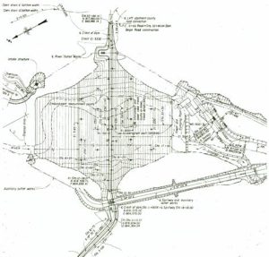
Figure 1a. Dam Construction Details Plan View (from Independent Panel, 1976)
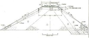
Figure 1b. Dam Construction Details Cross Section (from Independent, 1976)
Embankment Explanation
- Selected clay, silt, sand, gravel, and cobbles compacted by tamping rollers to 6-inch layers.
- Selected sand, gravel, and cobbles compacted by crawler-type tractors to 12-inch layers.
- Miscellaneous material compacted by rubber-tired rollers to 12-inch layers.
- Selected silt, sand, gravel, and cobbles compacted by rubber-tired rollers to 12-inch layers.
- Rockfill placed in 3-foot layers.
The Failure
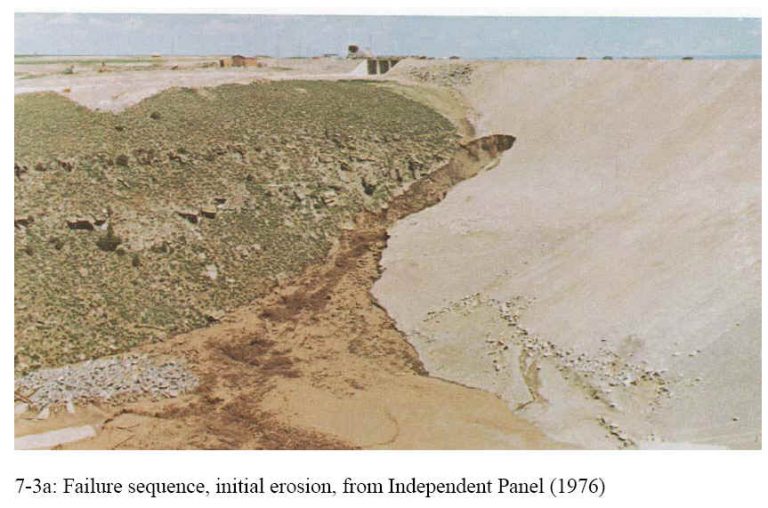
On June 3, 1976, several small seepages were noticed in the north abutment wall. Pictures were taken and these leaks were reported to the Bureau of Reclamation. This led to more frequent inspections of the dam. It was now to be inspected daily, and readings were to be taken twice weekly instead of once a week. On June 4, 1976, wetness was noticed in the right abutment and small springs were beginning to appear (Independent Panel, 1976).
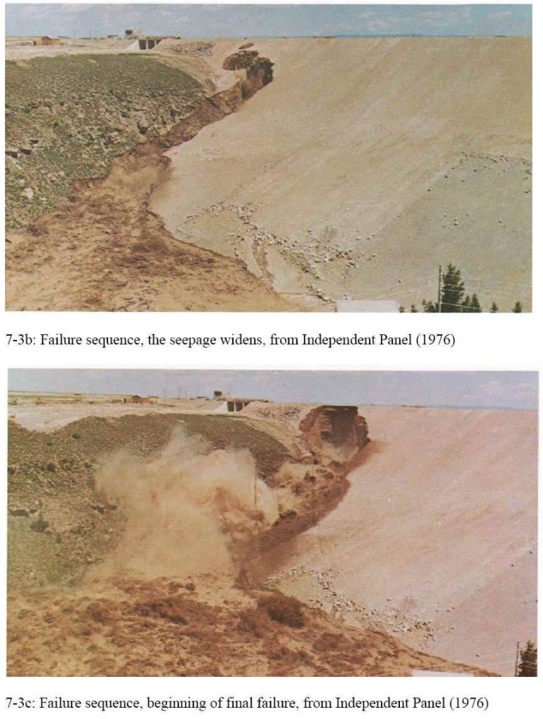
On June 5, 1976, the first major leak was noticed between 7:30 and 8:00 a.m. The leak was flowing at about 500 to 800 liters per second (20 to 30 cfs) from the rock in the right abutment. By 9:00 a.m. the flow had increased to 1,100 to 1,400 liters per second (40 to 50 cfs) and seepage had been observed about 40 meters (130 feet) below the crest of the dam (Arthur, 1977).
At 11:00 a.m. a whirlpool was observed in the reservoir directly upstream from the dam and four bulldozers were sent to try to push riprap into the sinkhole near the dam crest (Independent Panel, 1976). Two of the bulldozers were swallowed up by the rapidly expanding hole, and the operators were pulled to safety by ropes tied around their waists (Teton Dam Flood @ 2002). Figure 2 shows a cross section of the dam with the approximate locations of the seepage, the sinkhole, and a whirlpool in the reservoir noted.
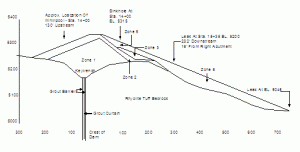
Figure 2. Initial failure indications (from Independent Panel, 1976)
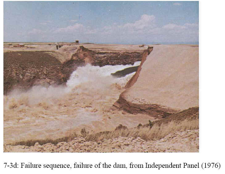
Between 11:15 and 11:30 a.m. a 6 by 6 meter (20-foot by 20-foot) chunk of dam fell into the whirlpool and within minutes the entire dam collapsed (Independent Panel, 1976). A slide gallery of the failure sequence, along with some photographs of the dam site today, may be found at http://www.geol.ucsb.edu/faculty/sylvester/Teton%20Dam/welcome_dam.html
The collapse of the dam may be seen at the U.S. Bureau of Reclamation website http://www.pn.usbr.gov/dams/Teton.shtml
At 10:30 a.m. dispatchers at the Fremont and Madison County Sheriffs offices were notified that the dam was failing. An estimated 300 million cubic meters of water (80 billion gallons) headed down the Upper Snake River Valley. The towns in its path included Wilford, Sugar City, Rexburg, and Roberts.
More than 200 families were left homeless. The final toll was 14 killed directly or indirectly and an estimated 400 million to one billion dollars in property damage. Some photographs of the damage downstream may be found athttp://www.lib.utah.edu/spc/photo/p211/p211.html
At the time of failure, the reservoir elevation was 1,616 meters (5,301.7 feet) and was filling at a rate of 1 meter (3 feet) per day. At full capacity, the water surface elevation would have been 1,621.5 meters (5,320.0 feet) (Bureau of Reclamation, 1983).
Investigating Panel
Following the failure, the Governor of Idaho and the Secretary of the Interior selected an independent panel to review the cause of the failure. This independent panel was made up of prominent civil and geotechnical engineers including Wallace L. Chadwick, a former president of the ASCE, and eminent geotechnical engineers Ralph B. Peck, H. Bolton Seed, and Arthur Casagrande. The investigators quickly developed a detailed plan, including field excavation of the failed dam down to the grout curtain and extensive laboratory testing. The panel began work almost immediately and issued its report in December 1976 (Independent Panel, 1976).
Panel Investigation and Results
The panel considered all possible causes of failure and tried to establish the sequence of events leading to the failure. During the investigation, conditions favoring erosion and piping were evaluated. Levy and Salvadori (p. 162, 1992) define piping as the development of tubular leak-causing cavities.
One of the first possible mechanisms considered was increased settling of the structure under the weight of the structure and the water, which would have led to cracking. It was determined that this did not contribute to the failure because the tunnel below the spillway would also have been cracked. Furthermore, earthen dams are relatively flexible and tolerant of differential settlements. The failure hypotheses eliminated included seismic activity, reservoir leakage, and seepage around the end of the grout curtain, as well as differential settlement.
Condition favorable for erosion and piping existed in Zone 1, where the primary materials were highly erodible silts. Wherever this material was subject to flowing water it could be attacked and washed away. This contact could have occurred in three different possible ways. First, seepage through the material could have caused backward erosion. This was determined not to play a major role in the failure since this process occurs very slowly. Second, erosion by direct contact could have occurred where water was in contact with open joints and thirdly, where there was direct contact through cracks in the fill itself. It was determined that these last two were possible and were probably occurring simultaneously (Independent Panel, 1976).
The key trench contained a grout cap overlying a grout curtain that was intended to stop the flow, but the investigation found openings and windows in the grout curtain near the failure section. The review panel also found that the construction of the grout curtain differed from the original design. The intended grouting procedure was to first grout the row of holes downstream, then grout the row of holes upstream, and then grout the center row of holes. This procedure was not followed during construction and the closure between the two outer rows, the center row of grout, was not made. Also, the spacing between the holes was not as specified and gaps were more likely to be present (Independent Panel, 1976). However, there is no way to determine if that had an impact on the erosion. Another impact on the erosion was that the topography near the key trench showed that the foundation was probably poorly compacted, which meant more rapid erosion could occur (Arthur, 1977).
Another cause of failure investigated was hydraulic fracturing near the leaks in the dam. Hydraulic fracturing causes cracking when the sum of the normal and tensile stresses exceeds the porewater pressure. It was determined that due to the cracks that had already existed, the pressure beneath the key trench was less than full reservoir pressure. In other words, due to the fact that the grout curtain was not fully effective, the failure was probably not due to hydraulic fracturing. However, hydraulic fracturing may have been a factor in the initial breaching of the key trench fill (Independent Panel, 1976).
The failure is best overall explained in the Review to the Department of Interior by the Independent Panel as, … caused not because some unforeseeable fatal combination existed, but because (1) the many combinations of unfavorable circumstances inherent in the situation were not visualized, and because (2) adequate defenses against these circumstances were not included in the design (pp.12-18, Independent Panel, 1976)
The panel summarized its conclusions (pp. vii-ix, Independent Panel, 1976):
- The pre-design site and geological studies were appropriate and extensive.
- The design followed well-established USBR practices, but without sufficient attention to the varied and unusual geological conditions of the site.
- The volcanic rocks of the site are highly permeable and moderately to intensely jointed.
- The fill soils used, wind-deposited nonplastic to slightly plastic clayey silts, are highly erodible. The soil classification was ML.
- The construction was carried out properly and conformed to the design except for scheduling.
- The rapid rate of filling of the dam did not contribute to the failure. If the dam had been filled more slowly, a similar failure would have occurred at some later date.
- Considerable effort was used to construct a grout curtain of high quality, but the rock under the grout cap was not adequately sealed. The curtain was nevertheless subject to piping too much was expected of the grout curtain, and the design should have provided measures to render the inevitable leakage harmless.
- The dams geometry caused arching that reduces stresses in some areas and increased them in others and favored the development of cracks that would open channels through the erodible fill.
- Finite element calculations suggested that hydraulic fracturing was possible.
- There was no evidence of differential foundation settlement contributing to the failure.
- Seismicity was not a factor.
- There were not enough instruments in the dam to provide adequate information about changing conditions of the embankment and abutments.
- The Panel had quickly identified piping as the most probable cause of the failure, then focused its efforts on determining how the piping started. Two mechanisms were possible. The first was the flow of water under highly erodible and unprotected fill, through joints in unsealed rock beneath the grout cap, and development of an erosion tunnel. The second was cracking caused by differential strains or hydraulic fracturing of the core material. The Panel was unable to determine whether one or the other mechanism occurred, or a combination.
- The fundamental cause of failure may be regarded as a combination of geological factors and design decisions that, taken together, permitted the failure to develop.
The Panel further described the geological factors as numerous open joints in the abutment joints and scarcity of better fill material than the highly erodible soil. the design decisions were complete dependence for seepage control on a combination of deep key trenches filled with windblown soils and a grout curtain,a geometry of the key trench that encouraged arching, cracking, and hydraulic fracturing in the backfill, using compaction of the fill as the only protection against piping and erosion, and failure to provide for the inevitable seepage (pp. ix-x, Independent Panel, 1976).
Another factor was the poor compaction of the aeolian silt fill material. It was compacted at less than the optimum moisture content. The material, as compacted in the dam, permitted continuous erosion channels (pipes) to be formed in the core without any evidence of their existence becoming visible. (p. 7-14, Independent Panel, 1976).
Lessons Learned
The lessons learned from this case may be divided into two categories. In addition to the technical aspects of the failure, professional and procedural factors also influenced the course of events. The lessons learned also have implications for engineering education.
Technical Aspects. The failure of the Teton Dam could have been avoided. Early investigations into the geology of the site showed that the rocks in the area were almost completely of volcanic origin. These volcanic rocks consisted of basalt and rhyolite. In the footnotes to the geological survey of January 1971, the rhyolite is defined as lightly to locally highly fractured and jointed, relatively light weight (pp. 4-7, Independent Panel, 1976). This was also the condition for other possible sites located upstream of the site where the dam was constructed. These materials are usually avoided due to a history of erosion and deposition. The reason for the extensive foundation was the poor quality of the underlying material, including the grout curtain. The grout curtain failed to do its job of preventing these materials from being easily washed away.
The panel noted that the design did not provide for downstream defense against cracking or leakage, and did not ensure sealing of the upper part of the rock under the grout cap. The grout curtain was not constructed in three rows, and the reliance on a single curtain was judged to be unduly optimistic. The dam and foundation were not instrumented sufficiently to warn of changing conditions.
Professional/Procedural Aspects. At the first sign of a problem, the people at the dam site informed the Bureau of Reclamation. The Bureau did not immediately inform the public due to fear of panic and because there were initially no signs of imminent danger, but the public was warned about 45 minutes before the collapse (Arthur, 1977). It was determined that the people involved acted responsibly and were not punished for their involvement. However, the failure of the Teton Dam brought about changes in dam construction and operation by the Federal Bureau of Reclamation to ensure safety.
On the 25th anniversary of the disaster, Ken Pedde, the Acting Regional Director of the Pacific Northwest Region of the USBR, reviewed the lessons that had been learned. Some of the changes in the process of dam design and construction include peer review of dams, special treatment for fractured rock foundations, and frequent site visits during construction by the design engineer. Also, redundant measures began to be used to control seepage and prevent piping (The Failure of Teton Dam @ 2001). Pedde’s address can be found at http://www.pn.usbr.gov/news/01new/dcoped.html
This failure also made each federal agency review their dam safety activities and Congress passed several acts that authorized a national Dam Safety Program. These reviews and programs brought about annual dam inspections and the installation of instruments to monitor dams. Also, the Reclamation Safety of Dams Act of 1978 provided funds to analyze and modify existing structures that were determined to be potentially unsafe (The Failure of Teton Dam @ 2001).
Educational Aspects. This case demonstrates the importance of engineering geology and geotechnical engineering for civil engineering students. Engineering geology is important for the evaluation of the suitability of foundation and borrows or fill materials. In this instance, both the rhyolite under the dam and the fine aeolian silt used as a fill material were deficient. Ironically, better borrow material was available in the valley downstream from the dam site, but the USBR decided that using it would be environmentally disruptive (Independent Panel, 1976).
It is also important to compact fill materials to the maximum density at or near the optimum moisture content. In this case, the material was too dry and was not sufficiently compacted (Independent Panel, 1976).
The static hydraulic pressure may also be determined using the height of the dam of 93 meters (305 ft.) and the height of the water of 86.1 meters (282.4 ft.). The pressure increased continually as the dam was filled. Also, this case can be used to review aspects of professional practice such as the responsibility of reviewing designs and using redundant measures to ensure the safety of the public.
From the failure of Teton Dam, many lessons were learned. One of these lessons is that a dam site must have solid foundation material. An effective grout curtain may be an effective way of dealing with this unsuitable material, but only if there is a way to check if the grout curtain is an effective barrier once it is in place. Also, this failure showed that dams must be designed so that pressure can be decreased if necessary. This was especially important in this case since the dam was allowed to begin filling while other parts were still under construction.
Summary and Conclusions
The case may be best summarized in the words of the panel report the Panel concludes (1) that the dam failed by internal erosion (piping) of the core of the dam deep in the right foundation key trench, with the eroded soil particles finding exits through the channels in and along the interface of the dam with the highly pervious abutment rock and talus, to point at the right groin of the dam, (2) that the exit avenues were destroyed and removed by the outrush of reservoir water, (3) that openings existed through inadequately sealed rock joints, and may have developed through cracks in the core zone of the key trench, (4) that, once started, piping progressed rapidly through the main body of the dam and quickly led to complete failure, (5) that the design of the dam did not adequately take into account the foundation conditions and the characteristics of the soil used for filling the key trench, and (6) that construction activities conformed to the actual design in all significant aspects except scheduling. (pp. iii-iv, Independent Panel, 1976).
In the design and construction of earth dams, it is necessary to select proper materials that are sufficiently resistant to piping and to ensure that they are compacted to the proper density. If a grout curtain is used, methods must be available to ensure that it is continuous and forms a seal with the underlying rock. The design should be incorporated adequate defense against cracking and leakage. Finally, dams must have sufficient instrumentation to provide early warning of piping and impending failure.
As a final comment, this case stands as a warning against overconfidence and hubris. As every dam engineer knows, water also has one job, and that is to get past anything in its way (p. 93, Macauley, 2000).
Print References
Arthur, H.G. (1977) Teton Dam Failure. The Evaluation of Dam Safety: Engineering Foundation Conference Proceedings, ASCE, New York, New York, 61-71
Independent Panel to Review Cause of Teton Dam Failure (1976). Report to the U.S. Department of the Interior and the State of Idaho on Failure of Teton Dam. Idaho Falls, Idaho. December 1976
Macauley, D. (2000). Building Big, Houghton Mifflin Company, New York, New York.
Teton Dam Disaster.Hearings Before a Subcommittee on Government Operations House of Representatives, 94th Congress, Second Session, August, 5, 6, and 31, 1976
Levy, Matthys, and Salvadori, Mario (1992). Why Buildings Fall Down. W. W. Norton & Company, New York, N. Y.
U.S. Bureau of Reclamation, Pacific Northwest Region, (1983) Teton Basic Project, Lower Teton Division; Idaho; Fremont, Madison, and Teton Counties.
West, Terry R. (1995) Geology Applied to Engineering, Prentice Hall, New Jersey.
Web References
U.S. Bureau of Reclamation, dam website http://www.pn.usbr.gov/dams/Teton.shtml
The Failure of Teton Dam, U.S. Bureau of Reclamation, News Release (online) available 6/5/2001 (2001). < http://www.pn.usbr.gov/news/01new/dcoped.html>
Teton Dam Failure (2002). <http://www.geol.ucsb.edu/~arthur/Teton%20Dam/welcome_dam.html>
Teton Dam Flood. (2002). <http://www.ida.net/users/elaine/idgenweb/flood.htm> (Dec. 23, 2002) – Survivor’s account
Damage downstream http://www.lib.utah.edu/spc/photo/p211/p211.html
Slide presentation http://www.xgiguy.com/Teton%20Dam%20Failure_files/frame.htm
Illustrations from Chapter 7 of the book Beyond Failure: Forensic Case Studies for Civil Engineers, Delatte, Norbert J., ASCE Press.
Vaiont Dam
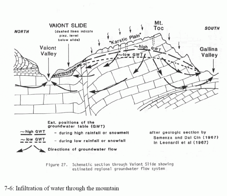
A slope stability failure is more commonly known as a landslide, particularly among non-engineers. This type of failure occurs when the weight of a soil mass overcomes the soils shear resistance along a failure plane. Water within soil increases its unit weight while reducing the shear strength. As a result, water and water pressures often play a role in triggering a slope stability failure.
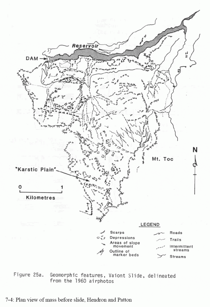
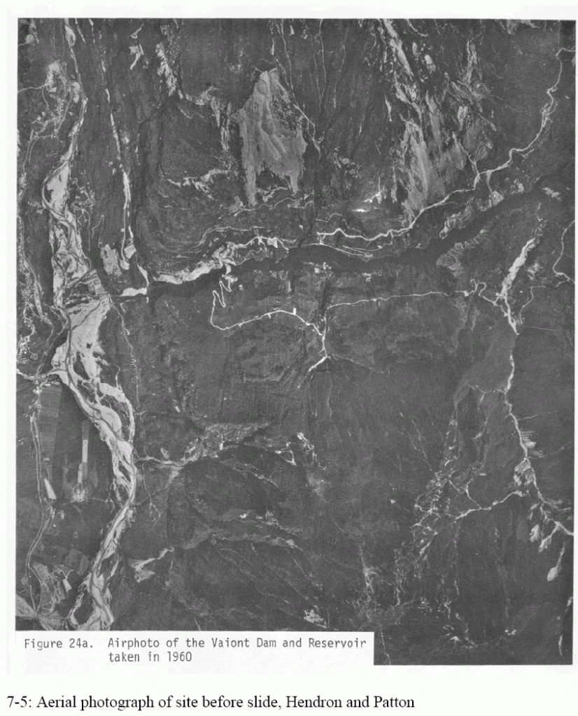
The Vaiont Dam disaster of 1963 was a classic slope stability failure. Ironically, the dam itself did not fail and stands today. The dam is a thin concrete wedge in a narrow gorge. A vast soil mass falling into the reservoir triggered a massive wave that blew over the dam and destroyed villages downstream.
The Vaiont Dam was part of an extensive system of dams, reservoirs, and hydroelectric powerhouses located in the Piave River Valley, high in the Italian Alps. The elements of this system were linked by tunnels and pipelines (Ross 1984, p. 131).
On October 9, 1963, at 10:41 p.m., approximately 270 million cubic meters (353 cubic yards) of rock fell into the reservoir, moving as fast as 25 m/s (82 fps). A tremendous wave of water blew over the dam, virtually the entire reservoir, sending a 70 m (230 ft) wall of water down Vaiont gorge. It destroyed the town of Longarone downstream, and severely damaged or destroyed the hamlets and villages of Villanova, Codissago, Pirago, and Fraseyn. 2,043 people were killed, including 58 of the utility’s employees (Wearne 2000, pp. 213-214). The population of Longarone before the disaster had been about 4,600. The flood also knocked out many access routes, hampering rescue operations (Ross 1984, p. 132).
The slide moved a 250 m (820 ft) thick mass of rock about 300-400 m (980-1300 ft) horizontally. It pushed the old slide mass up the far slope. Trees and soil along the Vaiont Valley were removed as high as 235 m (770 ft) above the reservoir level (Hendron and Patton 1985, p. 8)
The dam, however, stood. It had withstood a force of approximately 4 million metric tons (4 million tons) of water, roughly eight times the force for which it had been designed. The dam is still there, but there is no water behind it (Wearne 2000, p. 217-219). There was a small gouge in the concrete about 1.5 by 9 m (5 by 30 ft) along the crest near the left abutment (Ross 1984, p. 132).
The volume of the slide was slightly larger than the working volume of the Vaiont Reservoir. It was more than twice the volume of the largest earthen dam ever built, the Fort Peck Dam on the Missouri River in Montana. Because of the great volume, it was not practical to remove the material from the reservoir to restore the dams function (Ross 1984, p. 134).
The key document on this case study is The Vaiont Slide: A Geotechnical Analysis Based on New Geological Observations of the Failure Surface, Volume I, Main Text, Technical Report GL-85-5, published by the U.S. Army Corps of Engineers, U.S. Army Engineer Waterways Experiment Station, Vicksburg, Mississippi (Hendron and Patton 1985). It may be difficult to find except on loan from some large university engineering libraries.
The Vaiont Dam case study is covered in pages 206 through 225 of collapse by Wearne (2000) as well as pages 127 and 130 through 139 of Ross (1984). Wearnes chapter contains accounts from engineers and survivors of the disaster. Engineering News-Record reported on the case on October 17, 1963, and December 7, 1967, issues, and published an editorial in the October 24, 1963, issue.
A very similar mechanism caused the 2005 Bluebird Canyon landslide near Los Angeles, California. This case is featured on the Modern Marvels Engineering Disasters 17 DVD/video.
This case study is discussed in Chapter 7 of the book Beyond Failure: Forensic Case Studies for Civil Engineers, Delatte, Norbert J., ASCE Press.
Illustrations from Chapter 7 of the book Beyond Failure: Forensic Case Studies for Civil Engineers, Delatte, Norbert J., ASCE Press.
